14518 Brakes
Brake Assembly
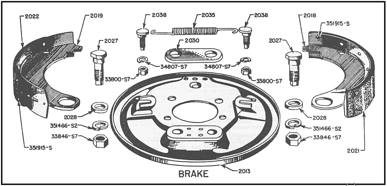
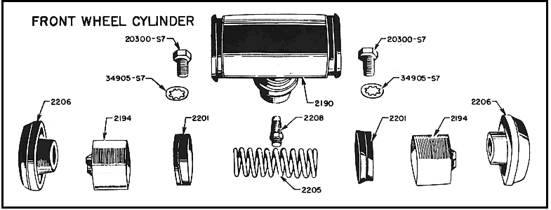
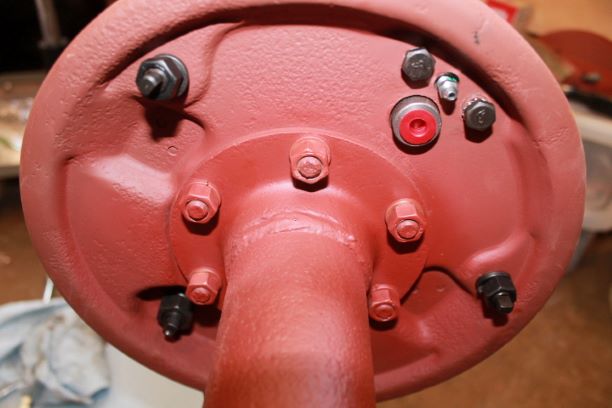
Installing the brake components on the rear axle are fairly straight forward. Install the parts as shown in the two parts diagrams above, then follow the brake adjustment procedures below.
I purchased all new adjustment cams and washers, new wheel cylinders and shoes. These are from Joe's Motor Pool and are all Ford or Kelsey Hayes marked components. I am pleased with the fit and finish.
I have read that one should use a bit of brake lube on the moving cam parts to ensure they don't corrode shut. Brake lube is supposed to be good to use as it will not attract the brake shoe dust and dirt as readily. I used copper anti-seize which is also recommended.
Everything went together well. I will use some matte clear spray for the cylinders to keep them from rusting, and they are originally left in the cast color. Since they tend to rust I used the flat clear.
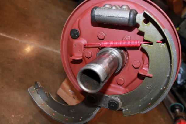
To install the cylinders I used F marked 1/4 x 1/2" NC screws. The originals were corroded, and measured 7/16"-ish. Also the original lower (heel) cam should have a dimple on the outermost edge to indicate orientation of the cam. I used a punch to mirror the original ones.
I have shown the shoes not fully installed so you can see the orientation of the upper adjustment cam.
I also used a scotch pad to polish the wheel spindle to make sure the bearings ride properly. There was a bit of corrosion from sitting. I covered them with oil for the meanwhile.
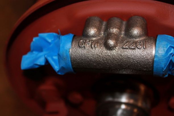
The last image is after spraying the cylinders with two coats of acrylic clear matter to prevent surface rust on the bare metal. The TM finish is specified as natural. I masked the rubber boots and the bleeder nipple so as not to damage the rubber or plug the bleeder valve.
A few extra notes that I have not mentioned.
- The brake shoes come with a long pad and a short pad. The SHORT pad goes on the side towards the REAR of the vehicle and the LONG pad on the side towards the FRONT.
- Remember that the wheel cylinders are different in front and in back.
FRONT: GPW 2061 1" cylinder
REAR: GPW 2261 3/4" cylinder
TM 9-803 Brake Adjustment
Installing the brake components on the rear axle are fairly straight forward. Install the parts as shown in the two parts diagrams above, then follow the brake adjustment procedures below.
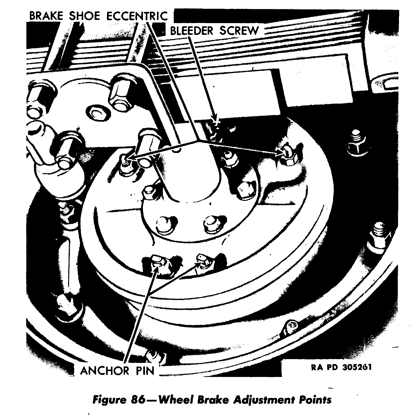
Adjustment (major). NOTE: Do not adjust brakes when drums are hot. Remove wheel stud nuts, and remove wheels from hubs. Insert 0.008-inch thickness gage through slot in brake drum, and turn drum so that gage is at upper (toe) end of forward brake lining. NOTE: Check clearance I inch from end of lining. Loosen eccentric lock nut on forward brake shoe. Place wrench on eccentric so that handle is up, and turn wrench handle toward wheel rim, or forward, until 0.008-inch clearance is obtained by feel of gage. Hold wrench on eccentric, and tighten lock nut. Turn brake drum so that gage is at upper end of reverse brake shoe lining. Loosen eccentric lock nut on reverse shoe. Place wrench on eccentric so that handle is up, and turn wrench handle toward wheel rim, or to the rear, until 0.008-inch clearance is obtained by feel of gage. Hold wrench on eccentric, and tighten lock nut. Remove 0.008-inch thickness gage, and insert 0.005-inch gage in slot. Turn brake drum so that gage is at lower (heel) end of forward brake shoe lining. Loosen lock nut on anchor pin of forward shoe. Place wrench on anchor pin with handle down, and punch marks on ends of anchor pins toward each other; turn wrench toward rim, or forward, until 0.005-inch clearance is obtained by feel of gage. Hold anchor pin and tighten lock nut. Turn brake drum so gage is at lower end of reverse brake shoe lining. Loosen anchor pin lock nut on reverse shoe. Place wrench on anchor pin with handle down, and punch mark on end of anchor pin toward other anchor pin; turn wrench handle toward rim, or to the rear, until 0.005-inch clearance is obtained by feel of gage. Hold anchor pin and tighten lock nut. Follow same procedure on the other three brakes. Check amount of fluid in master cylinder (par. 149), and apply foot brake pedal to test brakes. Bleed brakes if soft pedal is experienced (par. 151). Install wheel. Lower vehicle to floor.
Brake Lines and Fittings
There are quite a few things to do when installing the brake lines. Collect all the fittings, lines, hoses and brass Tee fittings. Make sure you have the copper crush washers that go under the threaded hose fittings. I elected to spray my metal lines with a celar cote to protect the metal from corrosion and provide some water protection to the asphalt looms.
The hoses and "S" fittings were installed during the front axle rebuild and assembly. This discussion includes everything up to those and for the rear axles, up to the wheel cylinders.
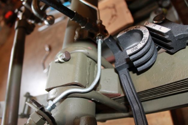
Starting with the front axle, the small tube that connects the left flexible hose to the Tee fitting was not bent correctly. I used my qangles bender to CAREFULLY bend the tube to meet the threaded parts of the flex hose and the Tee. It was easier to install the two nuts into the hose and Tee before securing the Tee to the axle. It took just a bit of slight sideways force to get them to align gently without kinking the tube.
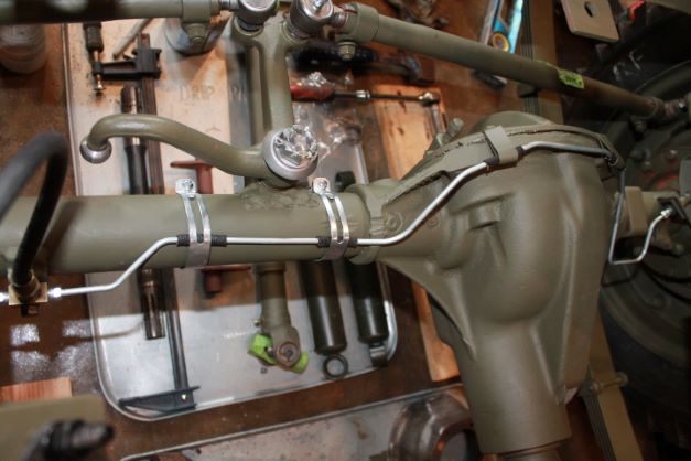
The long tube on the front axle is simple enough to install. I found it best to partially thread the nuts into the brass Tee and the Flex hose on the right side, then install the two brake line clips that go under the differential cover screws.
I took those two clips, bent them open and painted them. I slipped them over the loom on the tube, then bent them back flap. These were bent to conform to the tube, not the loom, so its a tight fit. I used a set of pliers to clamp the parts together so I could partially start the two screws through the holes in the clips. IA consideration is that the clamps are formed parralel to the cover line and the brake tube runs at a slight angle up to the top. It took a bit of coaxing to get the screws lined up to the cover holes and get everything to snug down without twisting anything. In reality, the back of the tube clamps should have a slight angle, or the metal tube should be parallel with the axle cover. From there they went in fine.
I then installed the the two clamps that fit over the axle. I found it was hard to fight these and do the diff clamps after, so these went in after everything was positioned. I needed to bend the tube slightly between teh right axle tube clamp and the left diff clamp, because there was only marginal clearance between the metal tube and the axle housing. I did not want any metal to metal rubbing. Everything was sprayed with
Master Cylinder and Brake Light Switch
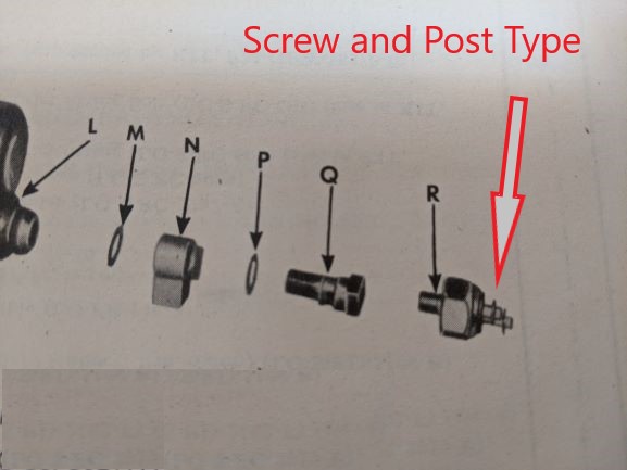
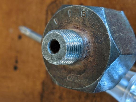
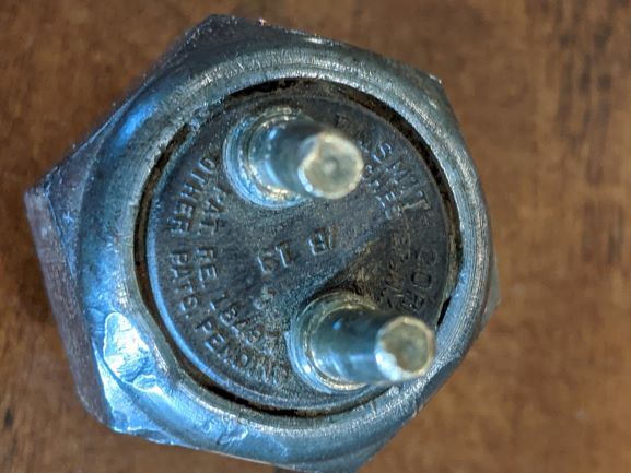
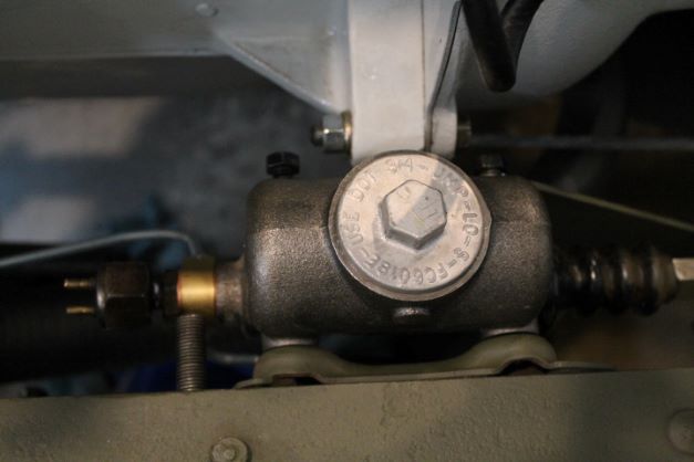
I am trying to confirm the type of connections that are correct for a GPW Brake Light Switch that is screwed into the end of the banjo bolt on the master cylinder. I have two from old projects, one is generic Stewart Warner, probably a replacement, and the other looks to be Ford marked. Both have the byonet style of connection. Some of the TMs and parts manuals indicate a post with screw for a ring connector. I am not sure where to go on this project,.
Here are some images of the one from a 1942 GPW (allegedly). It has the bayonet type attachments for the brake wires. The image below is from ORD- SNL G-503 Dated 15 Feb 45.
Master Cylinder Brake Lines
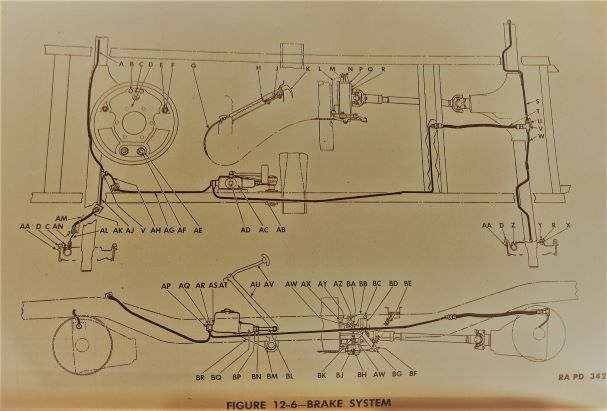
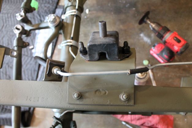
NOTE: The brake line routing for the MB and GPW are different. The main rear brake line from the MC is routed all the way through the frame for added protection and comes out at the MG mount crossmember.
Of course, I was watching the Team G503 Video and it is of course an MB. This is a continual consideration when doing detailed research on where to route things, what kind of hardware to use and bolt markings. I just need to to better research.
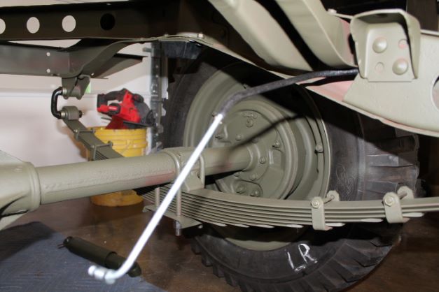
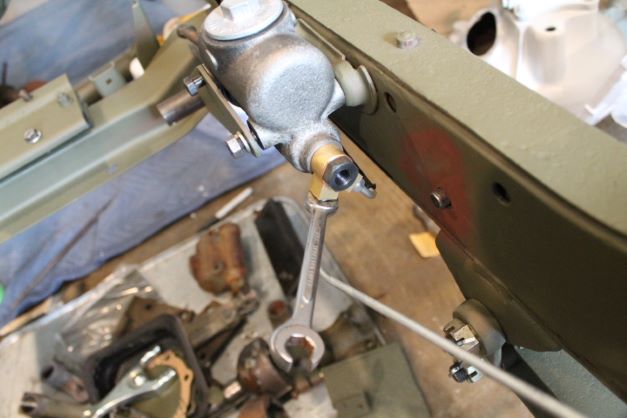
The images at right show the correct method (as far as I can tell) for routing the brake lines from the MC to the front flexible hose and read flexible hose to service the wheel cylinders.
There are two copper crush washers with different inner diameters for the banjo bolt at the front of the MC, and a copper crush washer where the flexible lines connect with the "Tee" fittings. It helps to install everything loosely, including the MC. This gives you a bit of flexibility to adjust things. I also found that the front MC line needed additional bending to match at the correct angle with both fittings. I will use the pictured fitting wrench to tighten later so as not to strip the nuts.
Rear Axle Brake Lines and Fittings
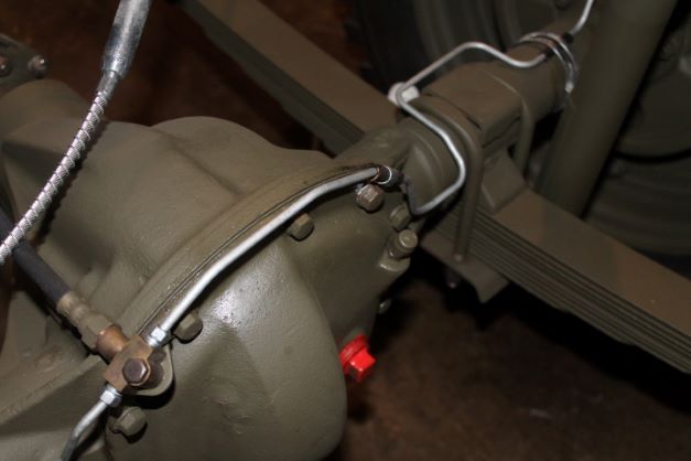
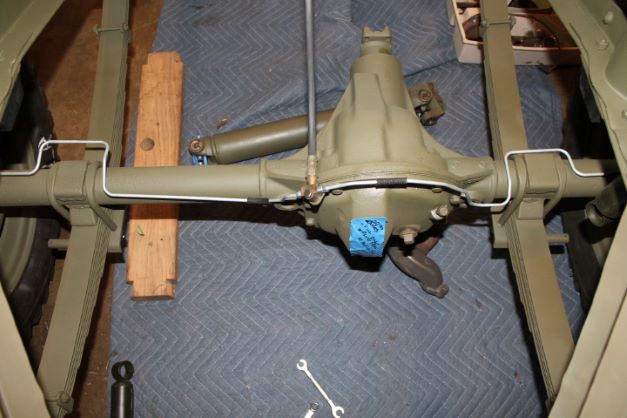
Installing the brake lines on the rear axle is relatively simple. I installed the flexible hose first with the crush washer and tightened that tightly down. I elected to keep the "tee" fitting loose, installed both lines to the wheel cylinders, and then one at a time installed the fittings into the "Tee" keeping everything only finger tight.
I finished all of the brake lines, clamps and fittings. I have the master cylinder installed and went back and methodically tightened all of the fittings. I neglected to use teflon tape to help seal the lower two fittings on the banjo bolt fitting in front of the MC. I had a leak which I could not get better than a minor drip. I suspect I tightened the fitting too much and the teflon tape will not work.
I understand teflon tape and DOT3 are not a good mix as the fluid dissolves the tape. In any case, I had no seepage whenre the tape was used.
I used a manual pressure bleeder to do the lines. I followed the instructions, but found the cheap pressure gauge on the bottle was not working properly. It did help me to ID a leak in my makeshift cap, and helped to bleed the lines without having to pump the brakes. I always hate this job as I never seem to get away from one or more fittings that seep.
Hand Brake Parts and Assembly
This is what the TM says about the Hand Brake Installation. It's not much help:
h. Install Brake Band to Transfer Case. Place the brake
band on the brake drum. Place the brake band springs between the
rear output shaft bearing cap and the ends of the brake band Install
the nut and bolt that secure the hand brake linkage to the rear output
shaft bearing cap. Insert the adjusting screw through the brake band
linkage, brake band springs, and install the adjusting nut. Install the
two anchor screws on the brake band.
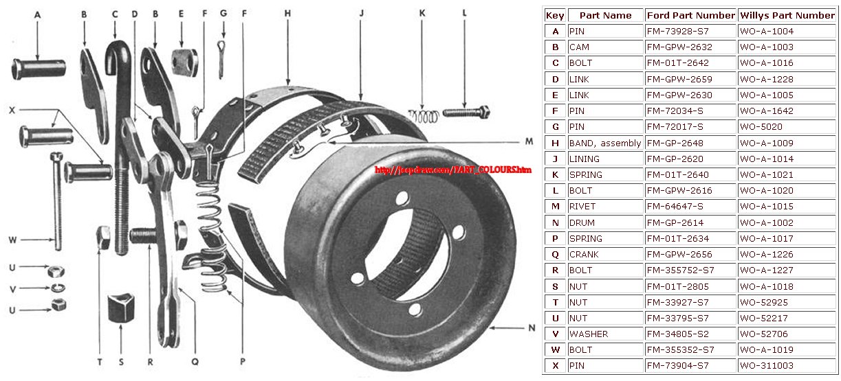
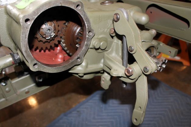
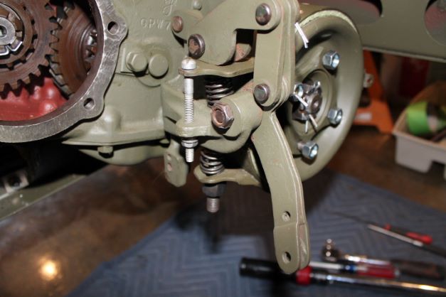
I found that it is easier to install the linkage first, because the large threaded screw holding the parts to the rear output shaft bracket will not fit in between the hand brake drum and its hole when the drum is in position. The rest is a matter of mirroring the diagram shown at right that comes from the G503 Jeepdraw page.
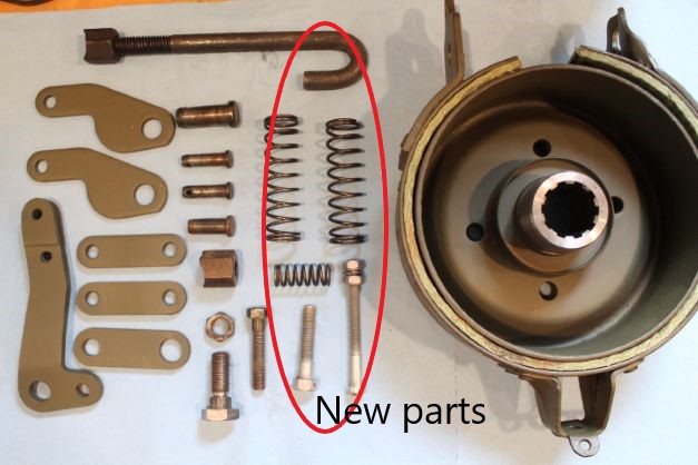
I cleaned up all my parts, and they are actually from an MB transfer case and the bolt (L) was AA marked. I used new springs and some hardware as shown at right in my assembly.
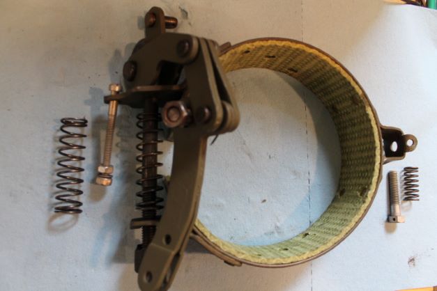
I found it helpful to pre-assemble all of the linkage to make sure the pins fit nicely. A small dab of anti-seize went on each pin. Here is an image of what I think is the proper orientation of the links and pins. Note the angle of the bends in the various links. It makes a difference in how everything fits together. Also note I did not install 2 springs on the dry fit.
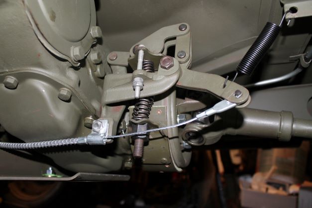
There is also a dry-fit of the linkage without springs to show where everything is connected. As I recall form my WC-12 drum brake installation, the 2 spring set up is a bit of a handfull to clamp and compress so that the scalloped nut can be started on the end of the large J-bolt. By dry fitting everything I was able to see that the reproduction J-bolt bumps up against the top plate on the band and will not allow the cam to compress the band. I am going back to the original J-bolt.
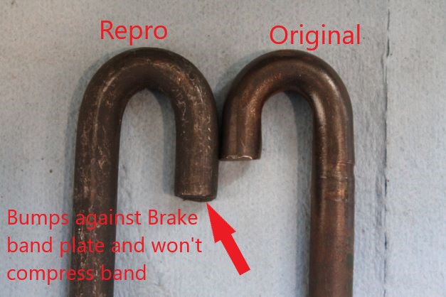
An additional problem is the spring that adjusts the right side of the band is so large that even when fully compressed it's length is greater than the space between the horn on the rear cap and the brake band. It physically will not fit in-between. I cut off three coils to make it fit when fully compressed. Here is the final picture before bending the cotter pins and final tough up.
TM 9-803 discusses the adjustment of the brake. Unless you turn your drum and have a perfect surface I found the feeler gauges to be useless. I simply adjusted the right side hex bolt until the band was binding and then backed it off until the drum spun with little resistance. Then I made the adjustments on the J-bolt lower nut and the long flat-head screw. Agin, just looking for no binding, and a tight hold when the cam is engaged.
a. Adjustment. Place hand brake grip in released position. Check
brake levers to see that cable is free and released. Remove lock wire
from anchor adjusting screw (fig. 91). Place 0.005-inch thickness gage
between band and drum at anchor screw, and adjust screw to secure
clearance. Install lock wire. Tighten adjusting nut until brake band
is tight around drum. Loosen bracket bolt lock nut and rear nut.
Back nut off two turns and set lock nut. Loosen adjusting nut so that
brake band has approximately 0.010-inch clearance on drum.
