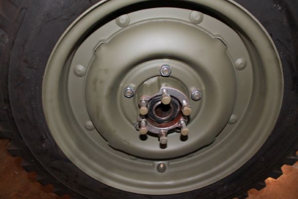
Wheels
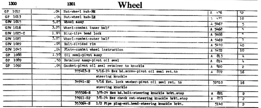
BEFORE
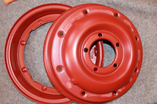
AFTER
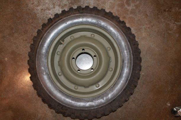
MDJ Combat Rims
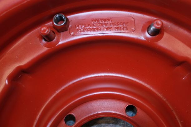
My GPW has CJ and M38 wheels which are solid rims. They do not look anything like the WW2 combat rims. While there are some decent condition original rims available, many have rust and damage around the lug holes and the safety of their use can be questionable. MDJ makes very safe 16 gauge combat rims with the Tire Inflation warning tags welded on in raised letters like the originals.
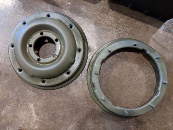
I decided to use four of the MDJ combat rims and leave an original on the spare just for show. I ordered four rims and they came in two packages, loosely tightened together. I removed the 8 rim nuts and using a rubber mallet was able to separate the halves. I am using 33070 Early Khaki Lusterless spray paint. I will give them 2 coats waiting 3 days between coats and probably a week to let them cure properly before mounting the tires.
There are many discussions about how to prepare the mating surfaces between the two halves to keep them from rusing together. Some say if you use primer and two coats of paint and do not run or store them in a water environment, they will not rust together. Others say to use something like rim grease or copper gasket spray to prevent the two halves from rusting together. I will probably use a bit of the copper gasket material where they mesh.
Combat Wheel Assembly
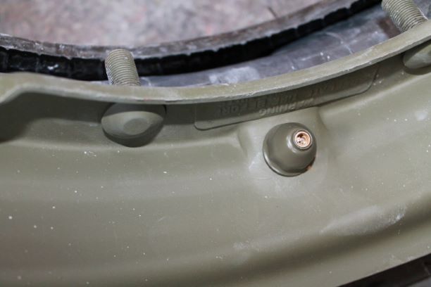
The first combat wheel assembly took 2 hours. Although I read many posts elsewhere, it was a bit of a trial and error method. The main problem was trying to get the stem to protrude correctly from the hole in the rim. The problem was that after several attempts to place the stem protector on, it would not protrude far enough to start the threads. More on that.
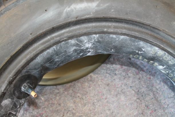
Talcum powder is your friend. Rubber on rubber does not move easily, but with LIBERAL use of the powder, you can slide the tube and flap in place and move them around to get everything to allign properly.
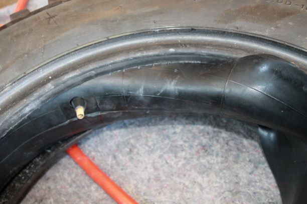
I began by slightly inflating the tube just enough to slide it into the tire. Getting the flap in is much easier if you fully insert one edge all the way around, then you can tuck the opposite edge into the tire around the tube. Of course you must align the flap hole with the stem.
Both the tube and the flap have an offset that corresponds to the offset hole in the combat rim. Order your tube with an ST-15 stem and your flaps with offset stem hole. Make sure the tube is not pinched between the flap and the rim.
Once the tube and flap are in place, use some soapy water and a brush or rag to douse the tire. It makes it slip on and off the combat rim easier. Place the rim half that has the stem hole over the tire and align the stem with the hole allowing it to fully protrude from the rim. This is the time to install the stem protector. You can push the stem through the hole fully from inside the tire as it is not fully inflated. This gives you enough protrusion to start the threads of the protector. Screw it down so that two or three threads are exposed above the protector.
Now you can install the other half of the rim, aligning the bolts with the holes and the groves in the rim with the lands. I made a crayon mark on both halves where they aligned to reduce the guess work.
Since the tube does not have much pressure in it you can press down on the rim and start the eight nuts on the protruding threads. Hand tight for now, then step them tighter a bit at a time tightening every third nut until all eight are snug. Then torque to 65-70 ft/lbs before inflating.
WARNING: Always deflate the tube before removing any of the nuts. There is a lot of pressure on the two pieces when fully inflated and people have been severely injured when rims separate under pressure during disassembly.
Installation of Wheel Bearings and Wheel Hub
FROM TM 9-803:
141. WHEEL BEARINGS.
a. Adjustment. Place jack under axle housing, and raise wheel so
that tire clears floor. Remove axle shaft (par. 140 a). Bend lip of lockwasher away from lock nut, and remove nut with box-type socket wrench (fig. 78). Remove lock washer. Spin wheel, and tighten wheel bearing nut until wheel just binds. Back off nut one-sixth turn or more, if necessary, until wheel turns freely. Install lock washer and lock nut. NOTE: Bend over lip of lock washer against lock nut. Check adjustment by shake of wheel. Install axle shaft (par. 140 b).Lower vehicle to floor.
b. Removal. Loosen wheel stud nuts. NOTE: Wheel studs have
left-hand threads on left side of vehicle. Raise vehicle so that tire
clears floor. Remove wheel stud nuts, and remove wheels. Remove
axle shaft (par. 140 a). Bend lip of lock washer away from lock nut,
and remove nut with box-type socket wrench (fig. 78). Remove lockwasher. Remove bearing adjusting nut and bearing lock washer. Shake wheel until outer bearing comes free of hub, and lift off wheel. Drive or press out inner bearing along with oil seal from wheel hub. Drive or press out bearing cups from hub. Clean old lubricant out of hub, and wash all parts in dry-cleaning solvent. Examine parts for excessive wear or damage, and replace if unserviceable.
c. Installation. Press bearing cups solidly into place in hub.
Spread 'A6 -inch layer of lubricant inside of hub to prevent rust.
Thoroughly lubricate inner bearing cone and roller assembly. NOTE: Pack lubricant into bearing cage. Install bearing in hub. Press oil seal into hub (with lip of seal toward bearing) until seal is even with end of hub. NOTE: Before installation, soak seal in oil to soften leather. Lubricate outer bearing cone and roller assembly. Install wheel on axle. Install outer bearing lock washer and nut. Adjust wheel bearings, and complete installation of parts (par. 141 a).
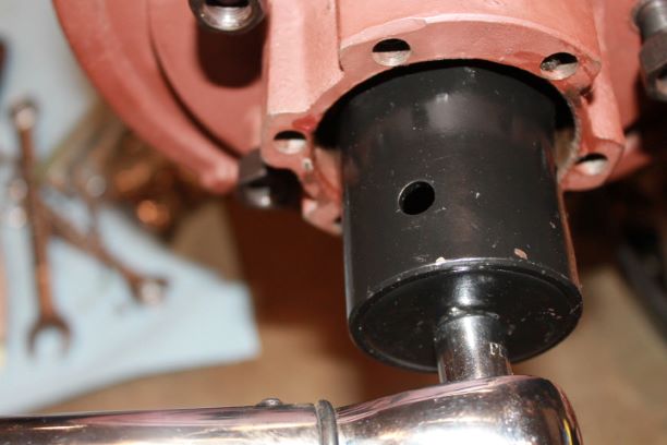
I followed the TM fairly closely except I used modern dual lipped oil seals. Do not drive them completely in, only flush with top of hub lip.
I used a socket wrench hub nut tool to torque to 50 ft. lbs. and then backed off 1/6 of a turn. This is to seat the bearings tightly as they are new. Backing off a bit brings the hub to a good pre-load, and when the outer nut is installed and tightened it wil add a bit more pre-load.
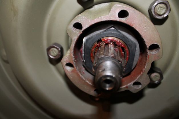
The order of the nuts and washers is not clear in the TM.
- First install the thicker washer with the tab in the groove.
- Install the first Wheel Bearing nut and torque to 50 ft lbs, and back off 1/6 turn
- Install the thinner washer with the hooked tab facing inward in the groove
- Install the 2nd nut and tighten.
NOTE: DO not forget to bend down the tab on the outer washer to "lock" the outer nut down.
When all is done and both wheels are installed, the final torque can be adjusted as required and the tab on the outer washer will be bent over the nut to prevent it from backing out.. Then the axles installed which will be detailed in the Rear Axle/Front Axle section. I'll snug all of the hub and wheel bolts down again to make sure I did not miss anything.
