GPW 14518 Electrical
Bonding Straps
I found sorting out the correct bonding straps to use for my April 1942 GPW a bit difficult. There are dozens of sites, pictures and discussions, but I found no complete listing.
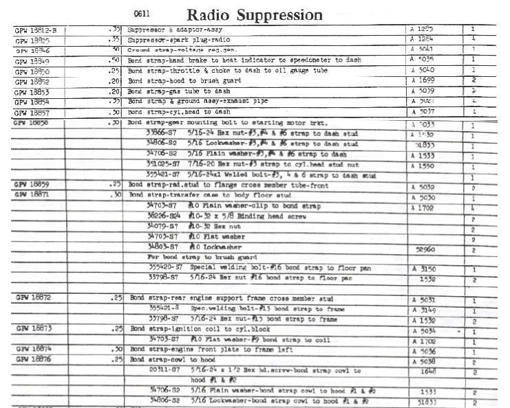
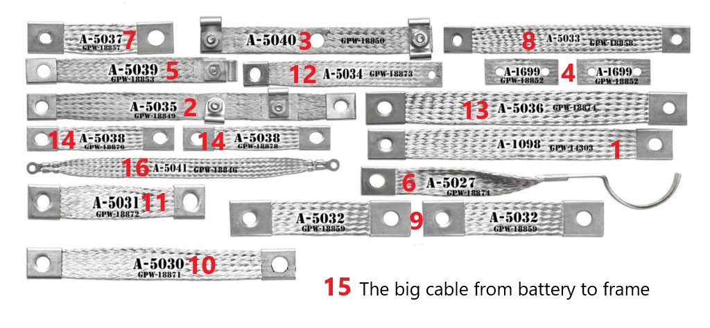
I decided to use the April 1942 Parts TM as a guide. The TM lists the following bonding straps numbered below. The numbers below are superimposed on the drawing of straps, in the lower right image, from the popular kits available for Early GPWs. There is quite a bit of tinning to do. I recommend getting the frame and body tinning done before any component assembly takes place on them.
BLUE Requires timming of the body
GREEN Requires Tinning of the Frame
BLACK Requires no tinning.
- GPW 14303, Bond Strap, Engine ground , Engine Support to Front Engine Plate (not shown on list at right)
- GPW 18849 Bond Strap, Hand Brake to Heat Indicator to Speedometer to Dash
- GPW 18850 Bond Strap, Throttle and Choke to Dash to Oil Gauge Tube
- GPW 18852 Bond Strap, Hood to Brush Guard (2ea.)
- GPW 18853 Bond Strap, Gas Tube to Dash
- GPW 18854 Bond Strap and Ground Assembly, Exhaust Pipe
- GPW 18857 Bond Strap, Cylinder Head to Dash
- GPW 18858 Bond Strap Gen Mounting Bolt to Starting Motor Bracket
- GPW 18859 Bond Strap, Radiator Stud Flange, to Cross Member Tube, Front
- GPW 18871 Bond Strap, Transfer Case to Body Floor Stud
- GPW 18872 Bond Strap, Rear Engine Support Frame Cross Member Stud
- GPW18873 Bond Strap, Ignition Coil to Cylinder Block
- GPW 18874 Bond Strap Engine Front Plate to Frame Left
- GPW 18876 Bond Strap, Cowl to Hood (2ea.)
- GPW 14301 Battery Strap Terminal to Frame Ground. (Not shown on list at right)
- GPW 18846 Bonding Strap, Voltage Regulator to Generator
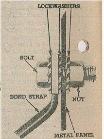
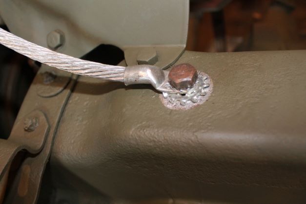
There are some hardware considerations that are detailed in the parts TM. As a general rule, Bonding Straps should be mounted with 3 star washers as shown in the image below.
What I Learned on the Way to The Tinning Factory
It took a while to begin to learn the techniques for tinning the bonding points on the GPW. Here is the basic process I used.
- Thoroughly clean the area to be tinned of all paint, primer and oils. Top Photo at right
- Using a high output propane torch, start to heat up the area to be tinned.
- Apply liberal amounts of flux to the area to be tinned in the pattern desired (Round or square)
- Heat the area again and touch the solder to the area to be tinned allowing it to flow over the metal and flux
- Wipe off excess solder and flux with a clean rag Center Photo at right
- Degrease the area
- Mask and Paint. I used a round piece of masking tape to keep OD off of the tinned area. Bottom Photo at right
Lessons Learned:
- ANY minor rust or primer will not allow solder to adhere. Top Photo at right shows small areas of primer in pitting.
- I am too impatient to wait for the electric iron to heat up the metal so I use a high temp propane torch.
- Placing some heat on metal before you add flux helps to allow the flux to flow where you brush it. I use the small cheap metal handled art brushes and buy them by the 4 dozen.
- If you hold the torch too close on High it blows the flux past where you want the tinning to go. To little heat and the flux will be a blob, Just the right amount makes it flow in a thin sheet. As soon as the metal reaches the proper temperature, the solder will melt into a pool.
- A wet rag helps to get rid of excess flux and solder after.
- Clean up afterward as with any painting process prior to masking.
- I use a circular hole punch to make round tape masks.
- It's best to work on a horizontal surface, otherwise the flux and solder runs down hill when it gets hot enough. Sometimes you don't have a choice. The masking tape and paint hides a lot unless you get it too thick (see the transmission mounting plate)
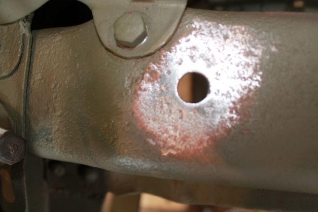
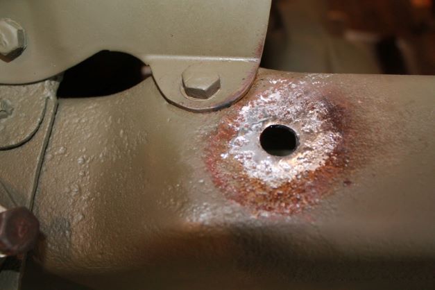
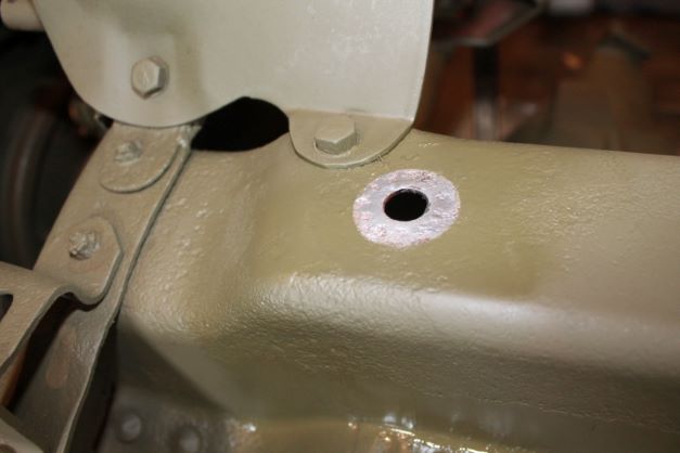
1. GPW 14303 Bond Strap, Engine Ground, Engine Support to Front Engine Plate
This area is a bit more difficult to solder when the frame is sitting on the axles. For this reason I would recommend doing all of your tinning before installing axles and springs.
Using a smaller circular grinding pad, I was able to get a nice round portion cleaned up and that helped me with the excess solder and flux. After tinning, it cleaned up fairly nicely.
For some reason I cannot locate the strap that belongs here. Will find and attach later. The other square tinned area was completed before the engine bracket was fitted to the frame. I have to research where that goes, and mask and paint again.
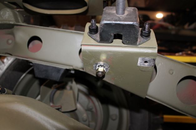
2. GPW 18849 Bonding Strap, Handbrake to Heat Indicator to Speedometer to Dash
THis bonding strap on the felt in the image grounds three items.
1: Emergency Brake Cable: This slides through grommet A and is clamped onto the driver's side air cleaner bracket using one of the special cable clamps, bolt, washer and nut. THere is also a grounding clamp which grounds the cable to the firewall via strap No. 2. Then it is routed under the transfer case, between it and the skid plate to the emergency brake linkage. THere is another special clamp that secures the cable to the back of the rear TC housing. The cable end is secured to the pawl using a pin and cottor pin.
2: Temperature Gauge lead is simply routed through the grommet, is grounded on the grounding strap that is secured to Point No. 2 and then into the egine block.
3. The Speedometer cable is routed from the speedometer, through the grommet and into the side frame rail and out to the connection boss on the TC. It is secured to the firewall via a screw at point No. 8
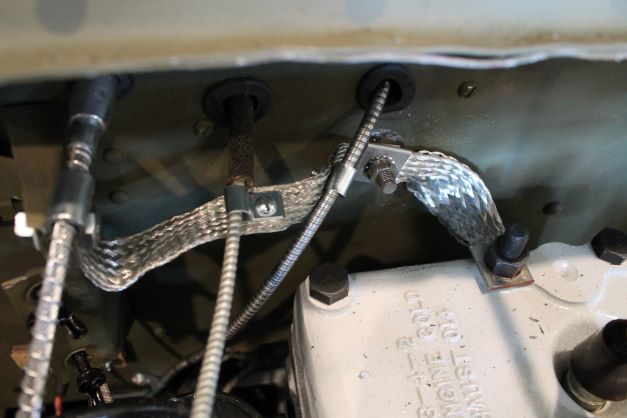
3. GPW 18850 Bonding Strap, Throttle and Choke to Dash to Oil Gauge Tube
When connecting ths strap it's best to connect the grounding brackets to the cable/tube first and then sip the bonding strap center hole over the stud in the firewall. The stud receives a star lockwasher, the strap, another lockwasher and then the nut. The choke and throttle cable have two clamps that fit togetehr and are held onto the end of the strap with one screw and nut. The oil line is done with a single clamp and screw/nut.
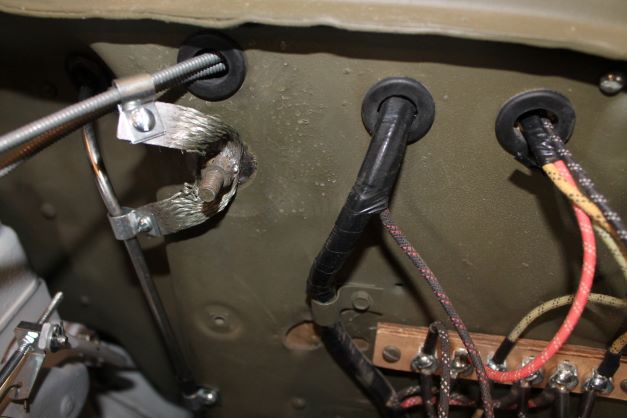
4. GPW 18852 Bonding Strap, Hood to Brush Guard (2ea)
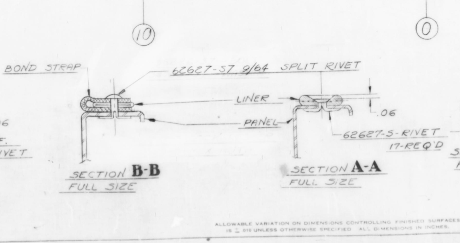
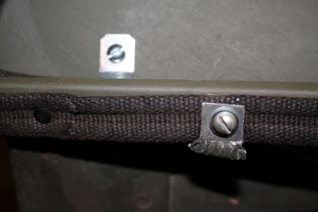
Two of these small bonding straps a mounted on the BRush guard, wrapped around the welting (hood to bruesh guard seal). The original Ford drawings show a rivet being used to secure the strap. I have seen many other restorations where a No. 10-24 screw, flat washer and nut are used. Since the rivets are not long enough in my opinion I elected to go with the screw.
The Ford drawing below with Cross Section B-B, details the order of assembly.
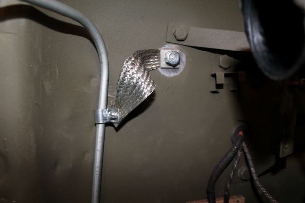
5. GPW 18853 Bonding Strap, Gas Tube to Dash
This location should receive tinning around the stud. Connect the clamp to the fuel line with a nut and screw and then secure the strap to the post with 2 star lock washers and a nut.
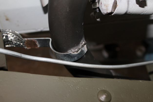
6. GPW 18854 Bond Strap and Ground Assembly, Exhaust Pipe
This bonding locations receives 2 grounding straps. The one for the engine, and this one, for the exhaust. I will attach them both, needing an extra star washer between the two straps, and then I will remove it later to weld to the exhaust pipe and re-attach it here. See No. 13 below for a finished picture.
Tinning this location which is at an oblique angle to the ground was not that difficult. I used a small grinding pad to make a circular clear spot through the paint and primer before heating and tinning. It made cleaning excess solder easier.
I forgot to mark the straps location to the pipe when it was on the engine and after bolting everything down I realized I had not welded the metal clip to the pipe. I did it in situ. Here is the finished product.
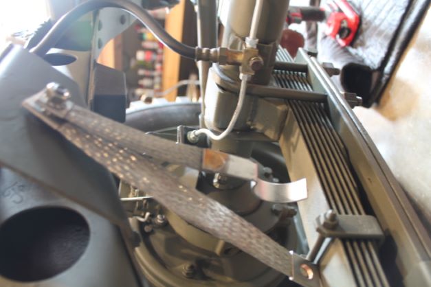
7. GPW 18857 Bond Strap, Cylinder Head to Dash
Before installing and torqueing the head bolts, slip the engine bonding strap over the rear center stud. When the engine is installed, it is easily connected to the center firewall stud as shown int he image.

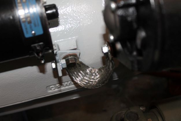
8. GPW 18858 Bond Strap, Generator Mounting Bolt to Starting Motor Bracket
I could find no reference to tinning at this location. I am hoping the star lock washers allow the trnsmission of electricity through the various components. In the starter parts section of the TM it calls for a 3/8-16 x 1 bolt to secure the bracket to the engine block. Hardware there is listed as plain washer and lock washer. Since the boncding strap goes there, I am adding two star lock washers. THe bracket to the starter support is listed as 5/16-24 x 5/8 with plain washer, lock washer and nut. I added tow star washers here as well. I am not completely sure on this configuration.
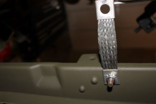
9. GPW 18859 Bond Strap Radiator Stud Flange to Cross Member Tube, Front
There are two of these bonding straps. They are not actually for the battery grounding system, rather for static suppression for radio emissions. The studs are welded to the inside rear of the front frame cross member. The straps have two different size holes. The smaller goes onto the stud with star washers and a 5/16-24 nut. The other end is bonded to the lower radiator stud, which is a larger diameter.
There are 2 of these straps to attach.
10. GPW 18871 Bonding Strap, Transfer Case to Body Floor Stud
I simply removed the bolt from this location and replaced the lock washer with two star washers and the bonding strap. Then I torqued the bolt back down.
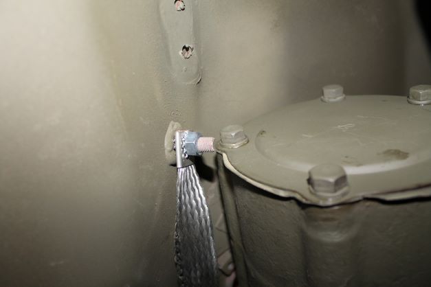
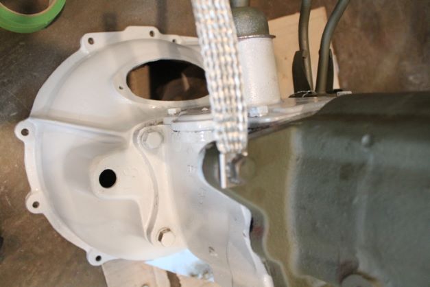
11. GPW 18872 Rear Engine Support Frame Cross Member Stud
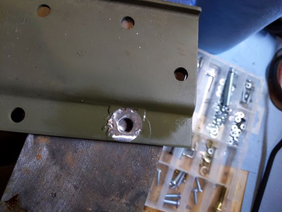
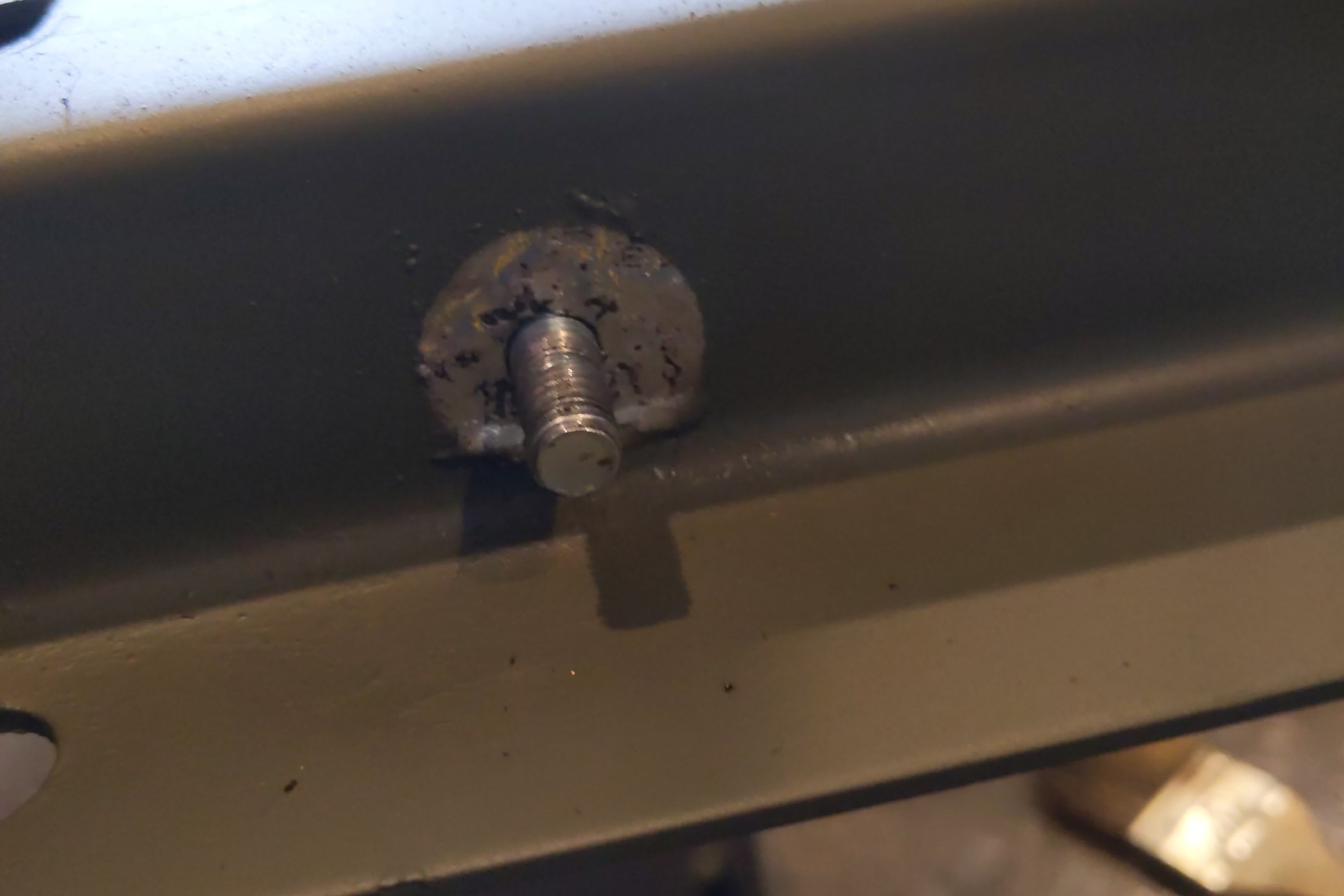
Installing this strap required tinning on two locations. I tinned the underside of the rear, left transmission mounting hole. The bolt that secures the transmission to the plate at the rear left mounting hole is where the grounding strap is secured.
This was my first tinning attempt and I used a technique of coiling a piece of solder around the hole and waiting until it melted. That ended up being too thick, so I had to grind the high spots down. You can also see where it pooled higher on the sides where the flux stopped. A better technique is to heat the metal, then touch the solder to the metal and drag it around in a circle. This makes for a thinner area of solder and a more uniform surface.
From this tinned area the strap is connected to the weld stud on the transmission cross member. That location was also tinned using the method described above.
Below is the finished grounding strap before the transmission is attached.
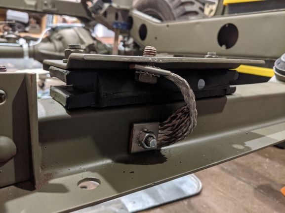
12. GPW 18873 Bond Strap,Ignition Coil to Cylinder Block
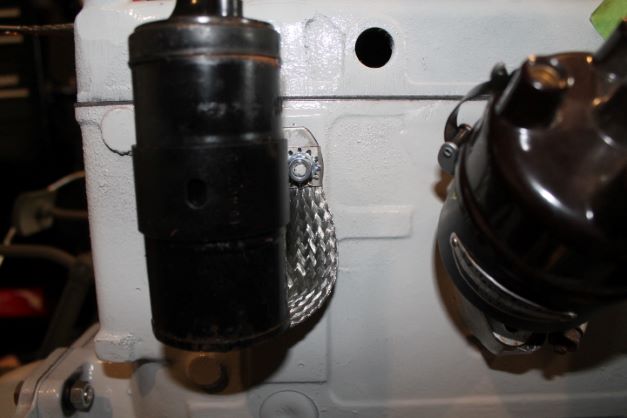
The bonding system on the 1942 GPW required a strap to be mounted from the lower grounding stud on the coil to the right coil bracket mounting stud on the engine. Ford used special "D" shaped washers with the F logo ont hem to secure the bracket behind these special washers. THere was a bit of debate on the G regarding the use of one or two of these washers, but as Tom W points out, the TM list 2 of them as:
GPW 12064 Washer - Coil Bracket 2ea
These were secured with 2 1/4" star lock washers and nuts. The grounding strap goes beneath the lock washer on the right side. Two star lock washers were used to secure the bonding strap to the lower coil stud with a nut. I cannot assertain if that is correct, but it follows the convention of ssecuring a bonding strap between two washers.
What may infact be correct for the bonding strap on the right stud is to use the 2 star washers on that side and only uise the special washer below the left side without a star washer.
13. GPW 18874 Bond Strap, Engine Front Plate to Frame Left
Little noteworthy at this location. Same details as with Item 6 above, only adding No 13, the Engine Bonding Strap to the stack. I'm leaving them loose on the bolt for now until I am ready to weld the curved position to the exhaust.

14. GPW 18876 Bonding Strap, Cowl to Hood (2ea)
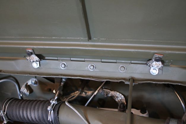
I am using the RFJP Hood mounting kit which comes with all appropriate hardware to attach the hood and grounding straps. Early GPWs had the grounding straps installed on the end holes, and later ones at the 2nd and 4th holes.
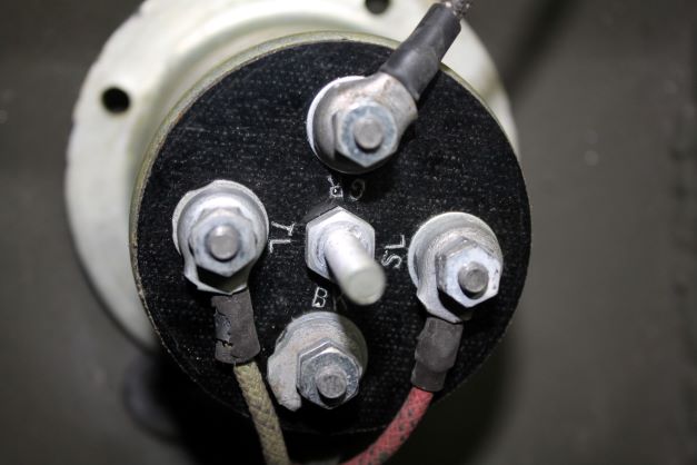
15. GPW 14301 Battery Strap Terminal to Frame Ground
This is supposed to be the most important grounding location. If the bonding surfaces between the metal frame and bonding strap are corroded or still have primer or paint on them, it will be more difficult to get the electorns flowing to where you need them.
I was pleased to see that when I cleaned the grounding location up there was the impression of a large star lock washer on the frame mounting hole. Later in production the grounding location was moved to the front right battery mounting hole.
I still need to confirm the hardwarerequired for this location. For now the bolt is 3/8 NF x 1" with a nut and 3/8 star washer under the frame surface. Then there is the large star washer, the bonding strap a 3/8 star washer and the bolt. The bolt should be S7 finish (cadmium plated). After installation in the factory the area received a light spray of OD to prevent corrosion. I will use flat clear to show the tinning, and perhaps tough up the OD later.
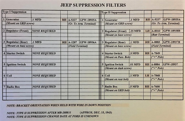
Radio Suppression Filters
WW2 Jeeps were equipped with a number of components to assist in supressing static discharge that emmitted from vehicles when operating near radios. This static discharge interrupted transmissions and reception and could prevent an important message from being heard.
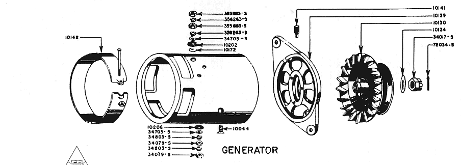
Each vehicle had items such as filters and bonding straps connected to electrical components to prevent spurious static discharge. The bonding straps were a big part of that as well as what is referred to a filterette mounted under the dash. On early GPWs Type I suppression prevailed and it also consisted of two small.1 MFD filters, one mounted on the generator as shown in the generator picture below, and another mounted on the rear mounting foot of the Voltage Regulator also shown below.
To my knowledge it has not been established at what specific date or serial number Ford converted to Type II suppression. It is speculated that the change occurred in mid 1944.
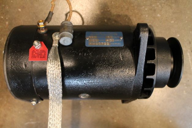
Generator
I was going to rebuild the generator and starter myself, but elected to take them to a rebuild shop near me. I dissasewmbled them and blasted the cases, used a rubber paint for the interior and semi gloss black for the exterior and took them to the rebuilder. I will tackle a rebuild on the next restoration, choosing this time to save some hours and spend a little more money.
NOTE: The Red Gennytag is not correct for a FORD Generator.
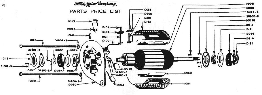
Starter
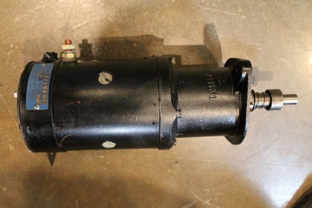
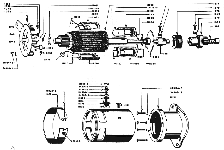
The starter was completely taken apart, cleaned and painted. I tiook everything including a new parts kit tot he rebuilder and the finished products is shown below. I added the Ford tag. I also replaced the bushing for the armature shaft that is in the bell housing and replaced the end cap.
A Note on Starter Switches
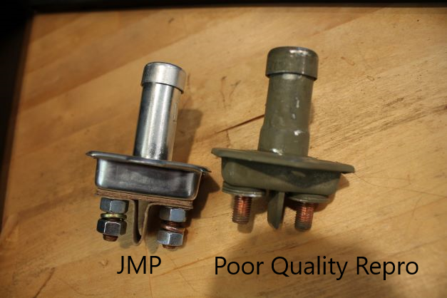
There is a large disparity in the quality of starter switches. Apparently the ones that have a stiff spring have a copepr contact bar that is substandard and the switch will fail rather quickly. I found that to be the case with mine. I just purchased a JMP switch and the spring is about 1/4 as stiff indicating that the copper contact bar is rather robust and will stand multiple cycles. I am installing it in place of the one I had.
Distributor IGC-4705
I have an old IGC 4705 distributor to rebuild. I removed it from my Jan 43 block and began to disassemble it. Although it looks to be in good condition, the shaft side play is excessive. I took everything apart and pressed out the upper and lower bushings. The springs appear to be worn and stretched, although the weights look good and swivel freely on the posts with no excess play in them. I have a distributor rebuild kit on the way. I also have a wartime copy of the Auto Lite TM with instructions and specs for the rebuild. The difference between the upper shaft diameter and the ID of the bushing was 0.0020" and at the lower end it was 0.0040" so I elected to replace the bushings. This week I will prep and repaint the case and when the rebuild kit arrives, I will assemble the new parts.
New bushings pressed in after soaking in 30wt oil. They slipped right in. Bottom bushing pressed flush and upper bushing pressed .094" into the sleeve. Case painted black. Will remove the tape and hit the clip mounts with a zinc color. As an added note I had bushings without the oil hole, so I followed the manual:
" On bearings without a hole, continue oil hole in base through bearing using a drill of same diameter. Remove burrs from inside of bearing being sure not to mar surface."
I measured the distributor shaft diameter. it is 0.500" top, middle and bottom where the bushings ride.
The bushings are slightly smaller at 0.4992" which is insufficient clearance for the shaft and oil passage. The manual indicates to fit the bearings to 0.0005" side play. That means I need to hone them to allow for the side play as specified in the manual. Side play is different from clearance between shaft and bearing, so this seems like a hone, measure, rehone process.
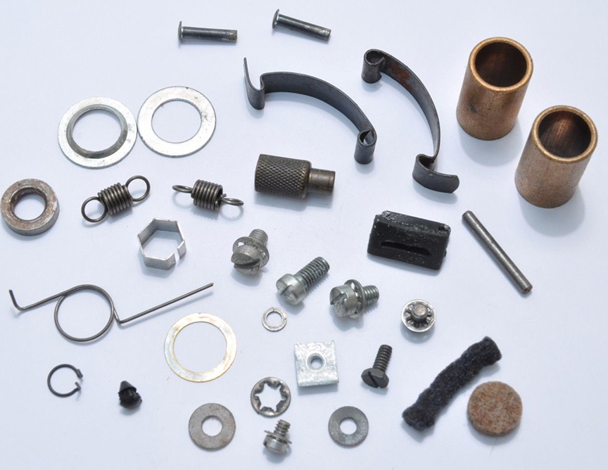
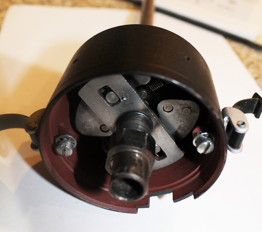
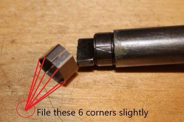
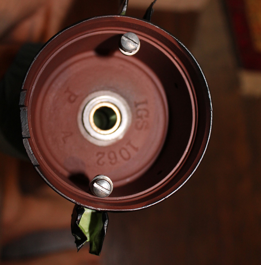
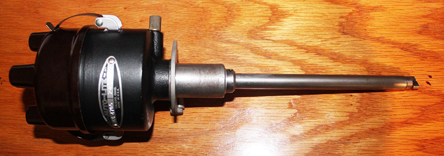
A potential problem exists when installing the anti rattle spring on the end of the distributor shaft. It will impede seating the shaft firmly to the oil pump. Kurt HostetterI of Willy's Distributors recommend the following and it works: "Just file the bottom corners of the shaft end rattle spring and a 45 degree angle to take the edge off. All you need is just a couple of strokes with a fine file per corner. "
I highly recommend him for parts and advice. He also does cvomplete rebuilds: www.willysdistributors.com
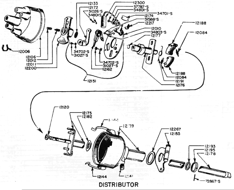
Take a look at the image of the spring and shaft at the left. NOTE This part is not shown in the early TM illustration posted above.
This spring is actually a very important part and many rebuilders are leaving it out. If you do not install it the end of the shaft can wobble and cause premature wear in the lower distributor bearing resulting in improper ignition. DON'T NEGLECT INSTALLING ONE!
actually rebuilt this distributor in 2017. If you wish to see the full adventure please reference the G503 at this thread:
https://forums.g503.com/viewtopic.php?f=4&t=288269&hilit=DIZZY
Voltage Regulator
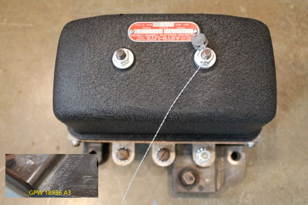
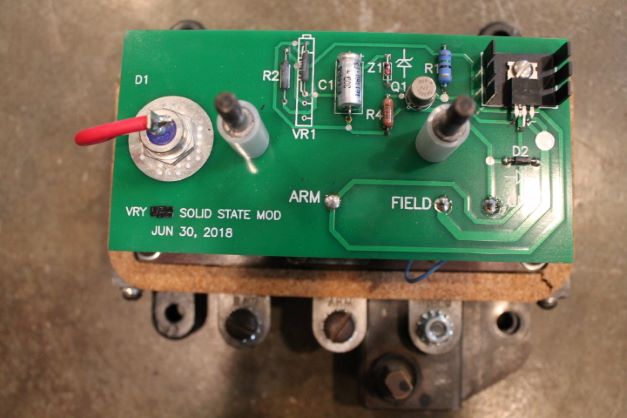
I do not know how to maintain the components of the old voltage regulators so I went with a solid state system. Others have had great luck with these. I repainted the cover with VR black wrinkle finish and installed the components. I was happy to uncover one of the hardest to find filters: GPW 18935. I left the nice patina on it.
Wiring the Firewall and Instrument Panel
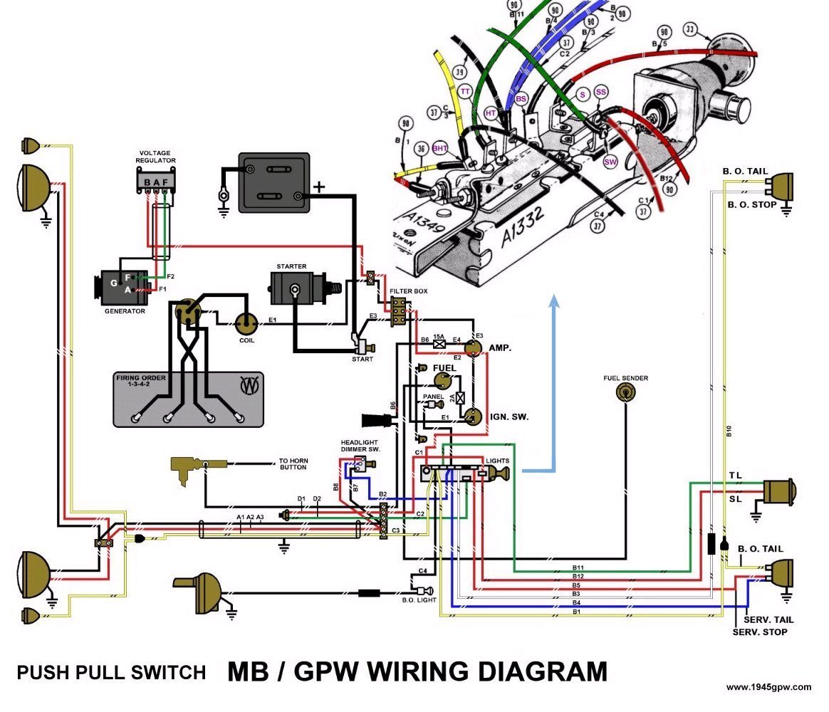
Wiring the body and behind the dash can be a challenging task. You don't need to undersand electrical fundamentals, you only need good diagrams and a correct wiring harness. I doubt one could make a harness from scratch for a lower cost than what the reproducers are offering. I would recommend just buying a correct one for your year and make. My harness did not come with junctions to wire the filterette, which is not a broblem at this point. I do not plan on connecting one and If I install a hinged box, it will not have the actual "guts"
I am not going to take pictures of the process, as others have done a better job than I could at this point. This could be a whole thread in itself, and many others have done the work before me. I would recomment the G503 and this site to research before starting:
https://willys.be/info/woa6758/woa6758.html
Here are a few Lessons Learned:
- I recommend that you study your wiring harness and label EVERY connector after determining where it goes.
- Study the wiring diagrams COMPLETELY before wiring anything up.
- Pay particular attention to where the long wires that route behind the dash go before hooking them up. Some go OVER the circuit breaker bracket. Otherwise you will have things hangind down.
- Purchase some extra nuts and star washers for the small screws behind the gauges and on the light switch.
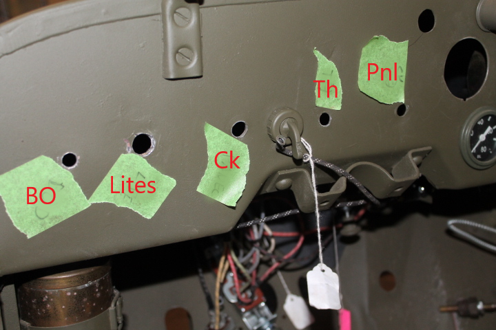
- Label ALL of the holes in the dash. I thought I would remember where everything goes, but in the end I was guessing.
I have a body that was pre-wired. I ended up removing EVERY wire and starting from scratch. I learned a lot in the process, and I also verified that it is connected correctly. There were a few wires improperly connected on the light switch. That would have been a headache to track down later.
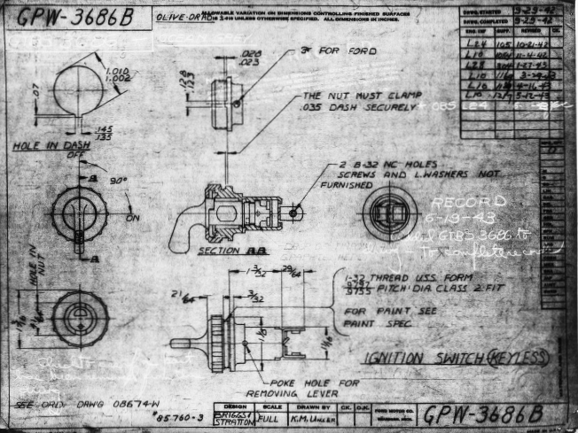
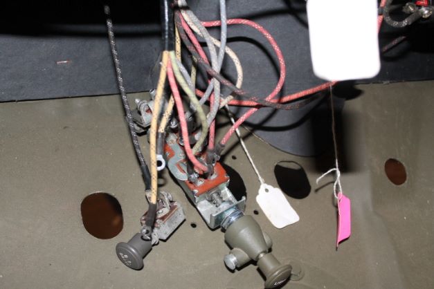
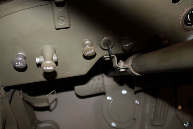
Here are two images at the right showing the dash with an extra hole above and to the left of the Fuel Gauge hole. It is not an original hole location for the GPW, So perhaps someone mounted an accessory or siren at some point. I have added a few images of wiring found on the G503.
Battery
I elected to keep my system at 6 volts in order to debunk the myth that it is insufficient to start and amaintain your GPW's electrical system. as long as the batter remains charged, the VR does its job and the grounding points do not get corroded, it should last for several years on a single battery.
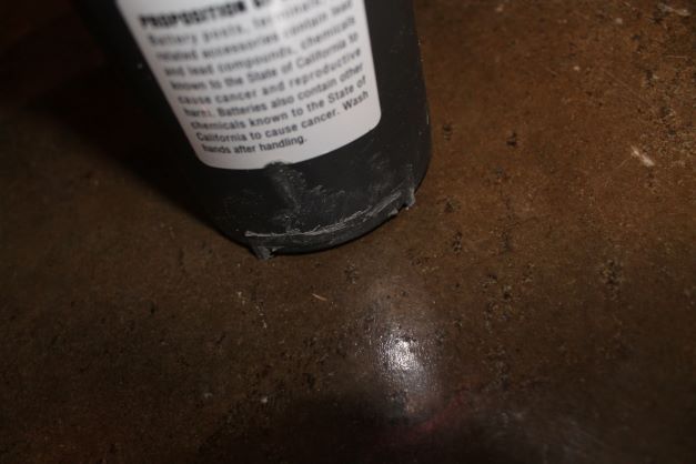
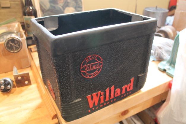
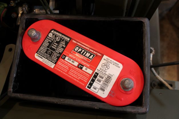
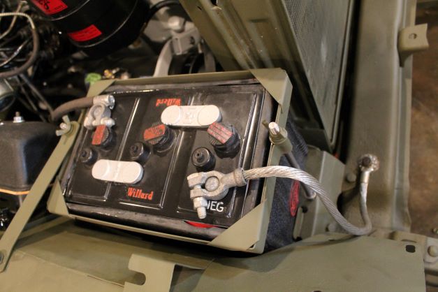
I elected to purchase one of Roblenzz' Reproduction Williard Battery shells and cover's. I found him on the G503. I am using the optima 6v 1000 CA/ 800CCA battery. The footers need to be ground off to get it to fit into the case as shown in the images.
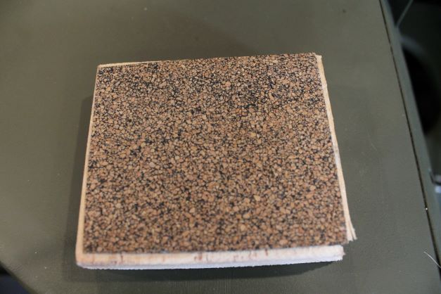
I made a simple stamp for the raised lettering and logos after attempting to do it free hand. It is a simple piece of rubberized-cork gasket material glued onto a block of wood. I used enamel paint, painted it onto the block, not too thick, and then carefully "stamped" the raised portion with a light to moderate pressure so as not to cause it to run into the cracks of the raised mold portion. I cleaned the pad between colors with paint thinner.
Amperage Gauge
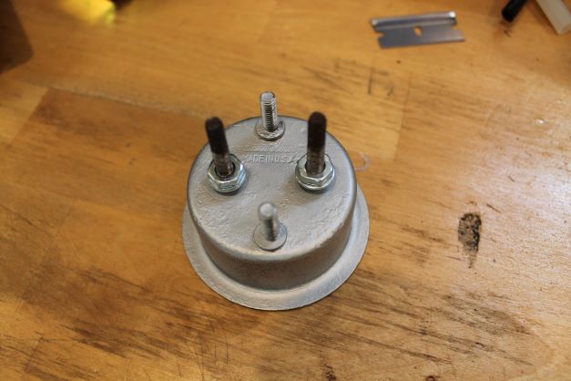
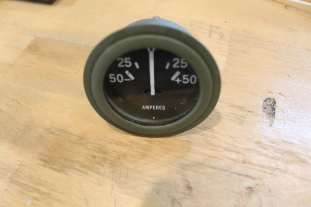
There are two types of gauges in the GPW. There are the early paint can style and the later crimp edge style. The crimp edge has a bezel with glass that is crimped over the edge of the gauge case, The paint style gauge gets its name from the way the bezel looks like the lid of a paint can. The paint can stlyle of gauges were used on VEP Fors GPWs and the really early ones possibly had a block style "F" on the bottom in place of the Stewart Warener log. There might be some remaining controversy regading when the F gauge was no longer used, and that is perhaps when the 8,000 or so Midland frames were used up. It is also postulated based on original unrestored GPWs with paint can gauges that those were out of use by "early" April 1942. This GPW is April 9 1942 and given it is a VEP production, I am installing the paint can style in mine and will be using the "F" marked gauge until I can get something more difinative.
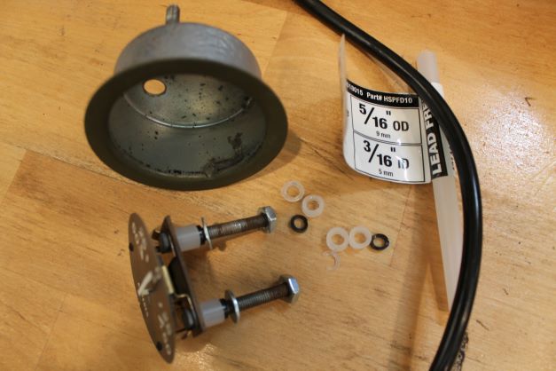
To resptre the gauge, I had to replace the ceramic insultars, which were cracked, with polyethelene tubing so that the case of the gauge is insulated from the wiring posts. If the posts make contact with the case in any way, the gauge will short out. Here is my work and the final product.
Lighting Switch
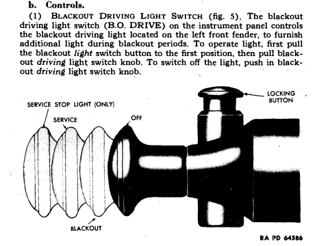
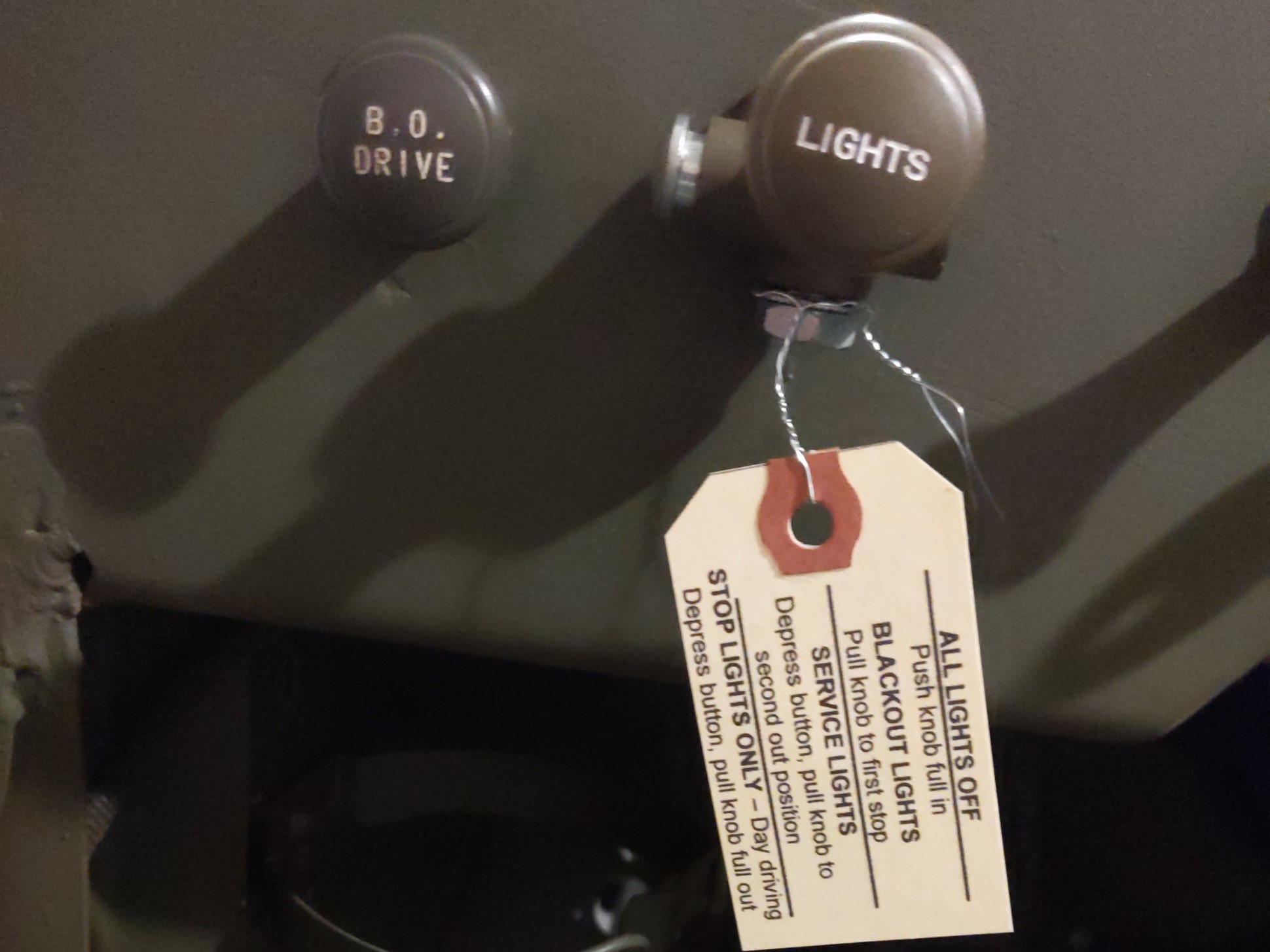
Most of the lights on the GPW are controlled by the main switch. The different positions and functions are explained in the TM, and on the G503 by "Quartermaster"
DAY DRIVING (lamp switch lock button depressed and pulled fully out - 3 stops on push/pull switch) This only activates your regular rear stop lamp (the big red one on the rear - driver's side) It is off until you step on the brake pedal and the stop light turns on.
SERVICE LIGHTS (for regular night driving (not blackout conditions) (lamp switch lock button depressed and pulled out 2 stops on push/pull switch) This activates the two front regular headlamps and the regular stop lamp (the big red one on the rear - driver's side) This one's illuminated all the time and step on the brake pedal to illuminate it brighter. The two dash board lamps are also activated and will turn on if you pull the dashboard switch.
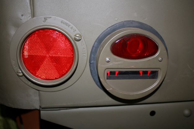
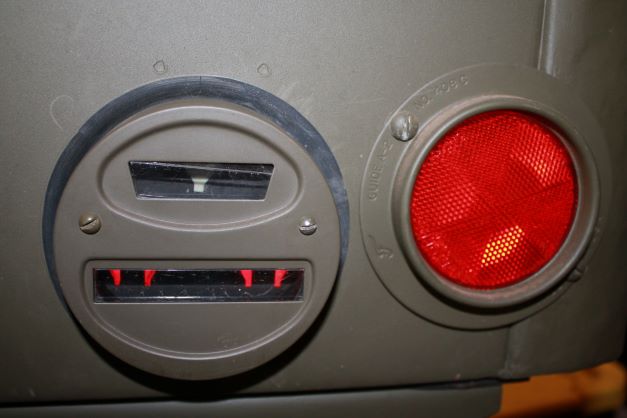
BLACKOUT LIGHTS (for use during blackout conditions) (pulled out 1 stop on push/pull switch.) This activates and illuminates the two front blackout indicator lamps and the two rear blackout indicator lamps (bottom half of both rear light buckets.) The rear blackout stop light is activated (the top lamp on the rear passenger's side) and will illuminate when you step on the brake pedal. The blackout driving lamp (on the front driver's side fender) is also activated and will become illuminated if you pull out the blackout lamp switch on the dashboard. Note: In blackout mode, the dashboard illuminating lamps cannot be turned on.
Lighting Continuity Testing
Rather than installing a lighting component, the wiring and hooking everything up to the battery to test it, I am doing a simple continuity check of each light as it is mounted. I use a simple voltage meter and in the continuity mode with tone, I connect one lead to the + wire of the light and the other end to a metal part of the body or fender. If I hear a tone, it means the ground of the light to the fender or body component is good and the light will work as advertized.
I've read too many people having lighting problems once EVERYTHING is hooked up and they have to start over tracking down where the problem is. THis method means I know that I have a good ground, a good bulb, and a good wiring connection to the light.
Black Out Drive Lighting
Black Out Head Light
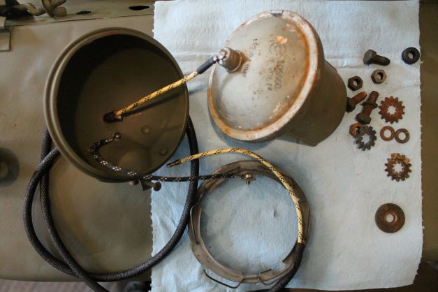
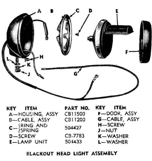
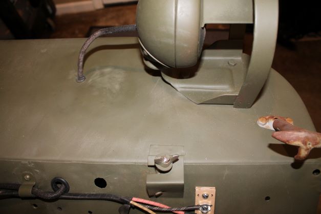
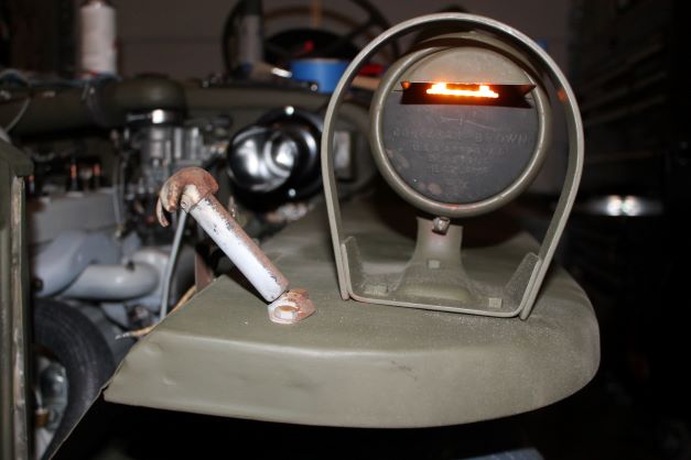
The installation of the Black Out Drive Light on early GPWs was done as a modification work order usually in the field. The kit included all items neccesary for its installation. Three holes were drilled into he Left Front Fender for the bracket and for the wire to come from underneath the fender. The wire goes through a hole that is above the hat channel and travels in the hat channel and back out into the engine compartment.
The diagram illustrates the assembly method. Be sure to allow metal to metal contact between the fender, the mounting bracket the threaded post and the brscket so that a good ground is established. ground comes from the fender. After assembling everything I used my multimeter and connected it to the line "G" that provides power and the other end to a part of the fender to make sure I had continuity. The light takes power from the BO Drive switch and groungs in the back of the housing "A" which in turn is grounded to the fender via the frame and the mounting bolts and star washers.
According to Ian Fawbert, there is an order to the hardware for mounting the bracket to the fender. It is as follows:
FRONT 2 bolts:
Bolt head
BO bracket
Fender
Internal/external GPW type tooth washer
split lock washer
nut
REAR bolt:
bolt head
BO bracket
fender
THICK (GPW) body bolt style FLAT washer
split lock washer
nut
Here is the assembly and then the finished product.
Service Headlights
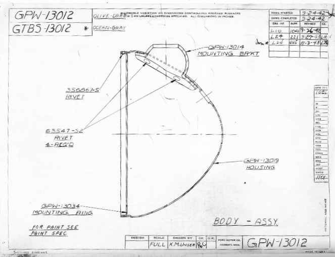
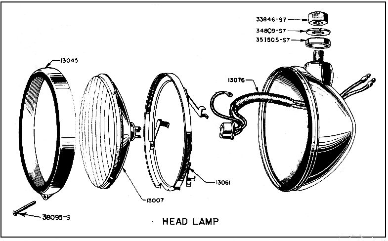
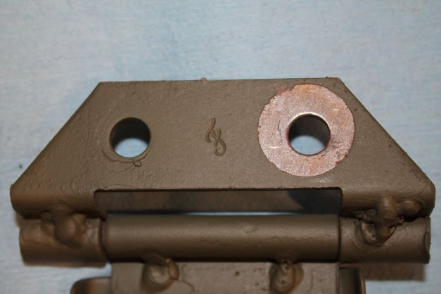
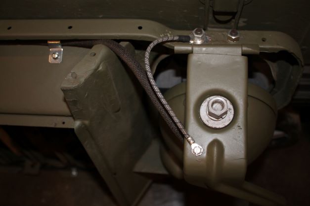
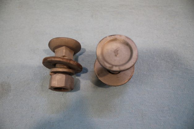
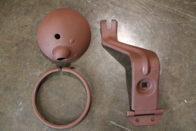
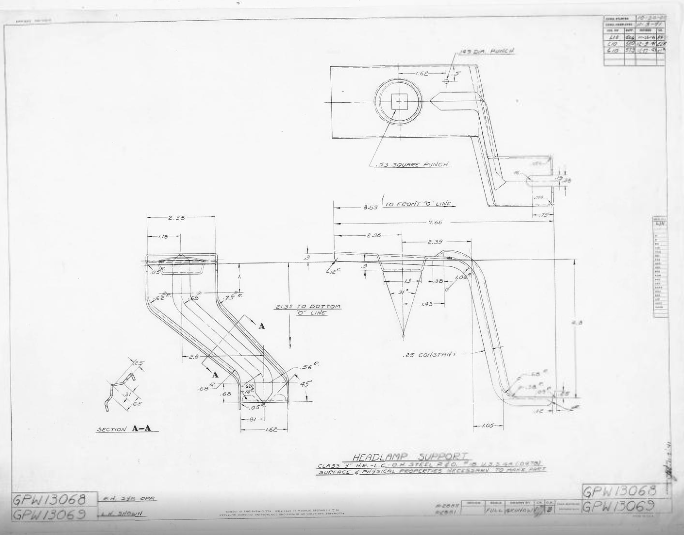
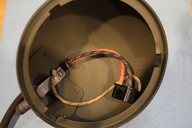
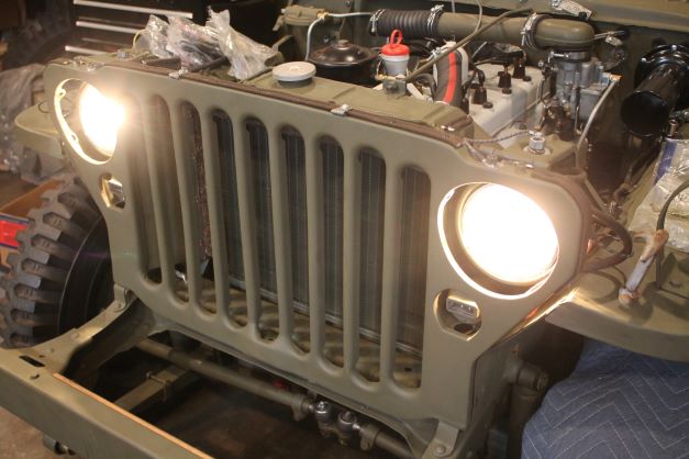
The headlights I have are all Ford marked and in great shape. One of the hinge brackets has been welded at one time. i ground down the welds a bit, sandblasted evything and primed. The bucket, ring and hinge bracket will get a few coats of OD. I will leave the top of the grounding bolt and the feeler arm unpainted so as to complete an electrical current. I did a bit of tinning on the hinge to allow a good contact between the grill and hinge.
Marker Lights
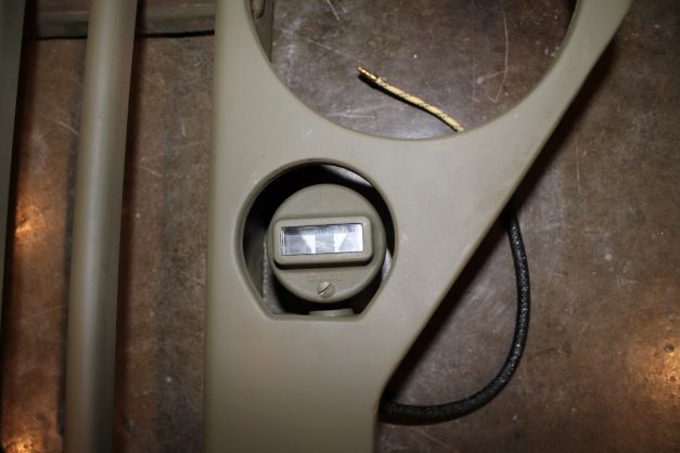
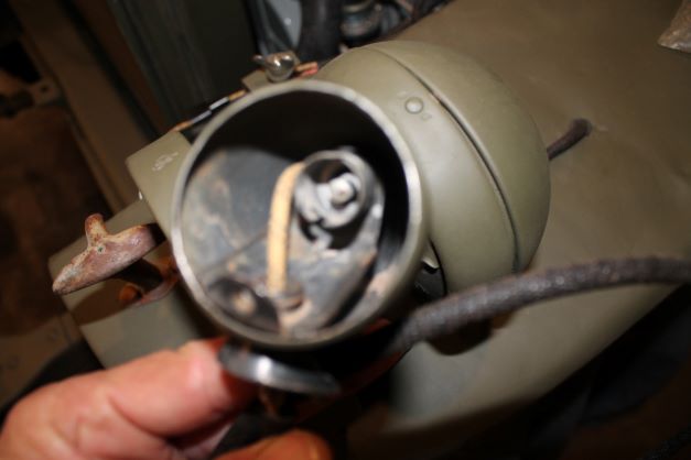
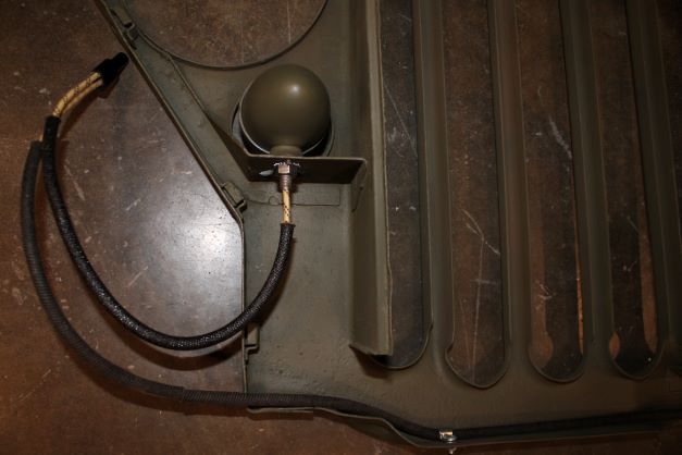
There are a few great posts on the web on how to replace the wiring in the marker lights. I found the easiet method was to drill out the knurled indents on the threaded post so that the interior assembly could be removed, cleaned and the new wire and post attached. Here is an image of the work in progress before final assembly/finish and one marker light installed.
My GPW should have no makers mark on the lens cover, and an "F" on the bullet housing.
The two marker lights are installed ensuring a good ground to the tinned area where the bolts passes through the grill and I added a star lock washer for good measure. The long line from the right marker is secured to the bottom inside of the grill with three small metal loom clips, screws and washers. The two marker light ends are connected with a 2-1 female connector.. This will in turn connect to the harness on the left fender.
Trailer Wires
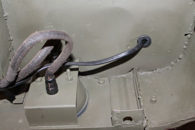
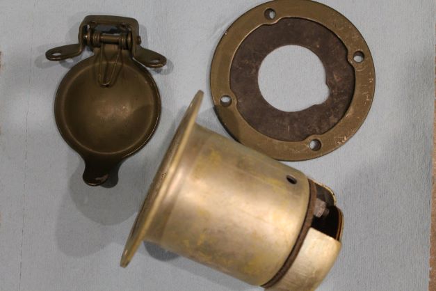
This is an early GPW which was not originally manufactured with a trailer socket. There was a field modification work order to retrofit the trailer socket onto the body. The wiring harness I have has the trailer wires already wired in, so I will drill the required holes, source a grommet and be ready to mout the socket when I am ready.
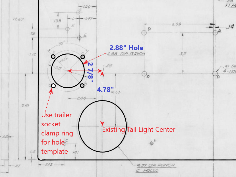
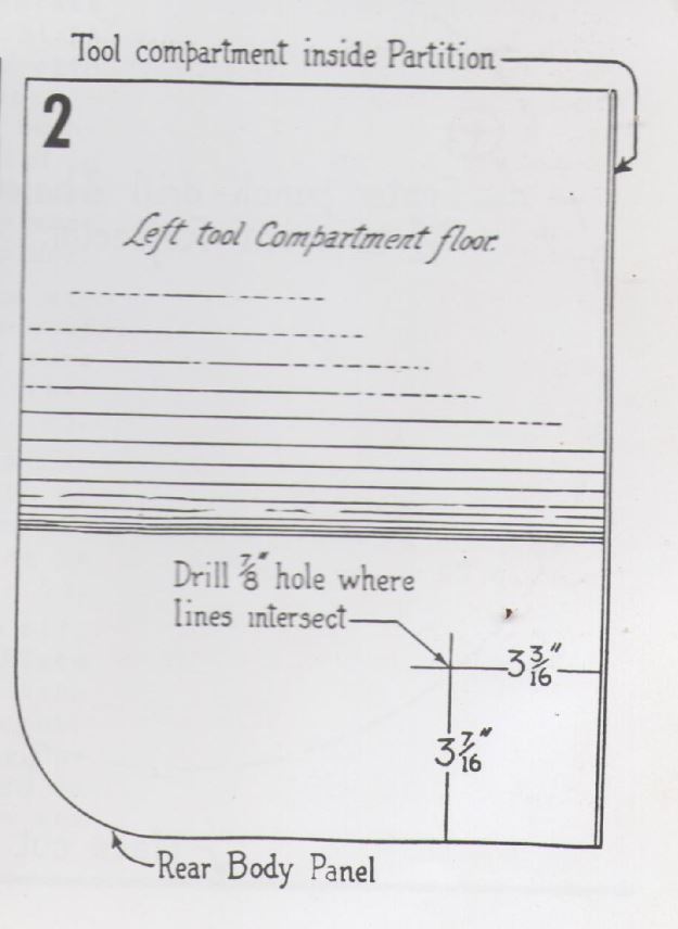
The FMWO came with instructions and a diagram for drilling the hole for the trailer wire. When I get around to installing it, I will add the details for the placement and wiring of the socket.
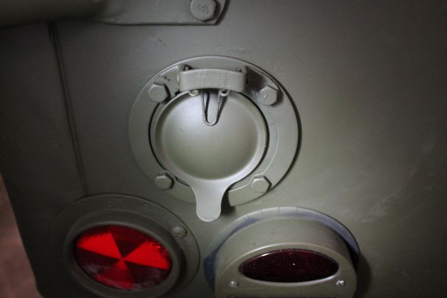
This may require the movement of the reflector as it was often done to accommodate the socket when the MWO was completed. THere are also cases of the socket just being placed without moving anything else.
There was also a ramp liek piece of sheet metal added to cover the wiring so as not to get damaged by the tools.
Trailer Socket Installation
From the TM, here are the instructions for installing the trailer socket:
c. Installation. Attach wires to terminals. NOTE: Attach GREEN wire to terminal "TL"; attach RED wire to terminal "SL"; attach small terminal of BLACK wire to terminal "GR." Install cover over terminals. To install socket in body, install the two long mounting screws in socket cover hinge. Place dust shield retainer ring over screws, followed by the dust shield with slot in center opening, opposite the hinge. Place cover against outside of body panel with the two screws through upper mounting holes so that cover opens upward. Place internal-external lock washers on each bolt. Install socket with drain hole down, and install lock washers and nuts loosely. NOTE: Toothed lock washers must be installed as directed for a good ground connection. Install the lower bolts with the lock washers in correct position. Install ground wire on a lower bolt, and tighten all four nuts holding socket in body panel. Install protecting cover, and secure in place with screw at top edge to complete the installation.
I
