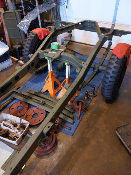
BEFORE
AFTER
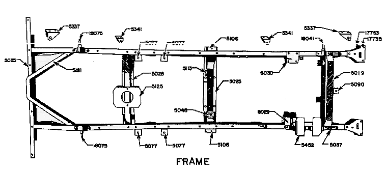
A Few Images of the Frame
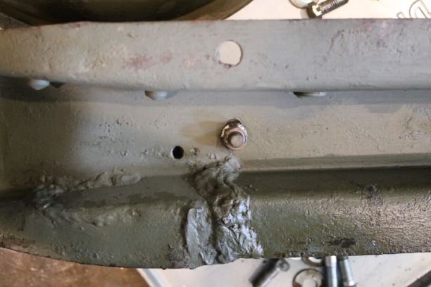
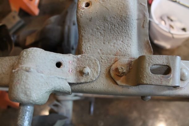
The frame is generally in great shape. There are a few areas of pitting, a welded repair and damage to the transmission cross member.
The transmission cross member on this frame was damaged in a previous life. It looks like there was a significant tear in the metal as there is about 6 inches of weld seam on different angles. Since there is a good bit of weight and torque on this component, I elected to use a reproduction piece for this.
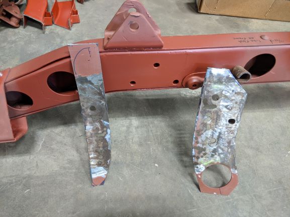
I have a scab on my frame where the steering box mounts. It has an 1/8" plate on the left and right side of the rail. I'm not concerned here, it's only a structural blemish. I don't believe there is much to do about this. I can't see that the frame was completely cut/broken at this point, not sure if a crack was developing, or if the mounting holes had been wallowed out so bad that they simply welded the plate on.
There are two areas of concern on the right front part of the frame. It looks like there was some heavy pitting in this part of the frame. The capture nuts on the rear of the body mount and the shock mount are quite eroded.
I'll have to take a closer look at the engine brackets to see what I need to do.A as the rear mounting bolt for the RS engine mount is gone.
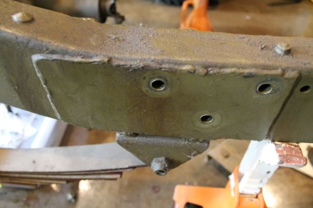
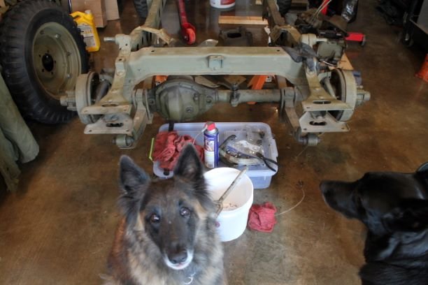
Frame Serial Number Stamp Identification
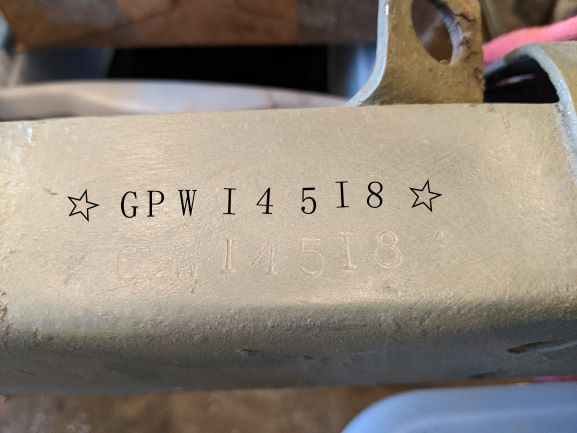
"Over the years I have come to know that the particular manner of stamping of the Ford data tags, the engines and the frames can provice definitive information regarding the plant at which the particular GPW was assembled. Componenets were manufactured at various locations by Ford and their contracted suppliers, and shipped to the assembly plants.
Ford had plants in Dearborn MI, Louisville, KY, Dallas TX, Chester, PA, Richmond, CA and Edgewater, NJ. There were one or more technicians who were responsible for stamping the frames. The manner and style, angle of letters, depth of stamping, use of the STAR or double arrow head, and variations in the font of the "W" in GPW can help to determine which plant produced your particular GPW."
The "Jeep Whisperer", Tom W.
In the case of GPW 14518, Tom has determined that my GPW was produced at the Richmond CA plant on 16 April 1942 and would bear a US Army Registration Number from 20106375-20106475. Without finding the original stencils below coats of paint, one cannot determine the eact "Hood Number" as the Army was responsible for assigning those to the GPWs and it is not an exact numeric sequence, sadly.
In any case, GPW 14518 was at the early part of the 2nd Contract.
Cracked and Bent Engine Mounts and Other Concerns
I have the frame fully sand blasted and primed so that I can work on the challenges that it offers. I have there areas of concern.
The frame horns have been heavily modified and welded on. The metal is fatigued and bent. I fear that if I try and heat and reshape and add a bit of welding I will end up with more bending and warping down the road. I ended up ordering two new front frame horns with the front spring shackle brackets. As soon as they arrive, I'll work on replacing them after some more research.
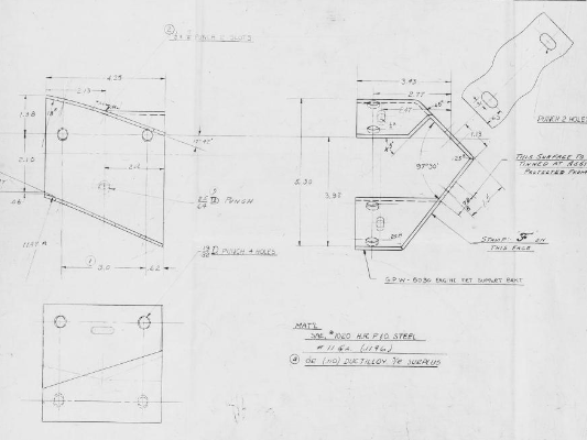
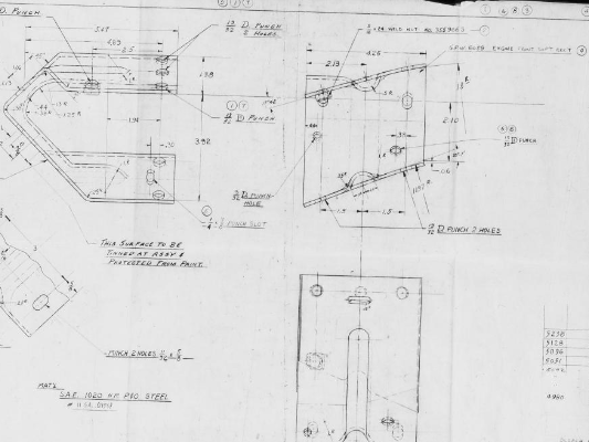
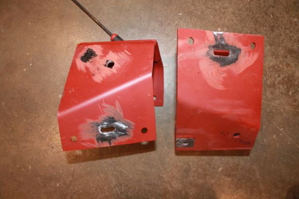
The motor mounts are most concerning. The RS mount had three splits in it, it is severely deformed and bent downward and somewhat collapsed. The LS bracket is also bent downward and exhibits stress cracks. Trying to return them to the original shape will be like re-bending a spring. It may hold for a while, but probably not my best option. I elected to use the MDJ motor brackets. I am a bit displeased with them as they are not completely drilled and they are welded with two pieces. Perhaps that makes them stiffer, but they do not look accurate, but at least the configuration is true. I will ahev to add holes for the grounding straps and the 1/4" slots for the welding support.
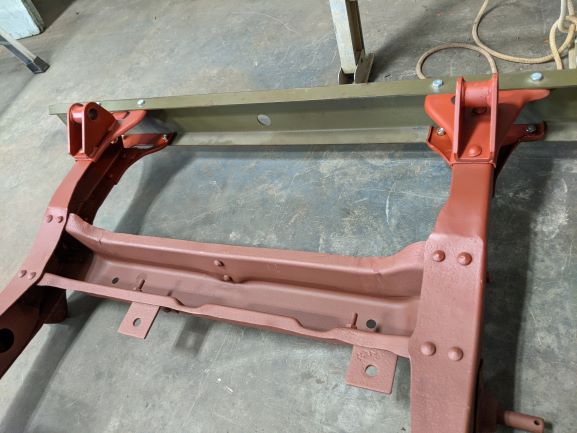
A final area of concern was my transmission cross member. It hit a sizeable rock in a previous life, was bent upward and backward and was welded in several places where the member had split. Again, I don't want to use a piece which has taken such abuse and fatigue and is critical to the drivetrain structure and support. The MDJ part is accurate in the profile, but the four vertical hole mounts are not drilled in the correct location. I will weld, grind and re-drill the four holes.
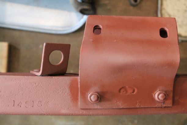
Below on the right are the finished motor mounts. The reproduction mounts are not completely drilled per the Ford drawings. I added the 1/4 welding slots, the remaining holes as indicated in the drawings and I tinned the area for the grounding strap. I just need to weld on the 5/16" welded nut.
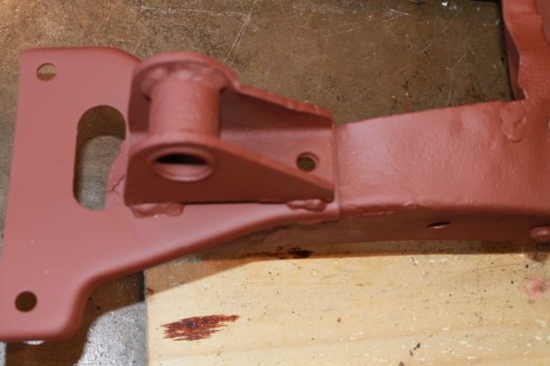
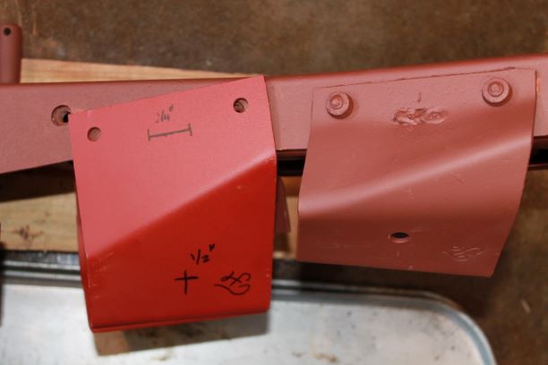
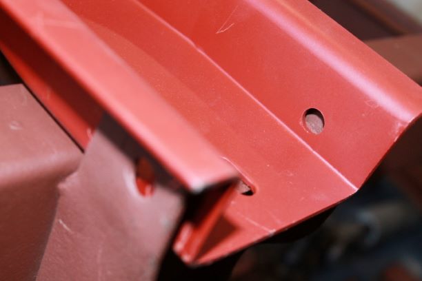
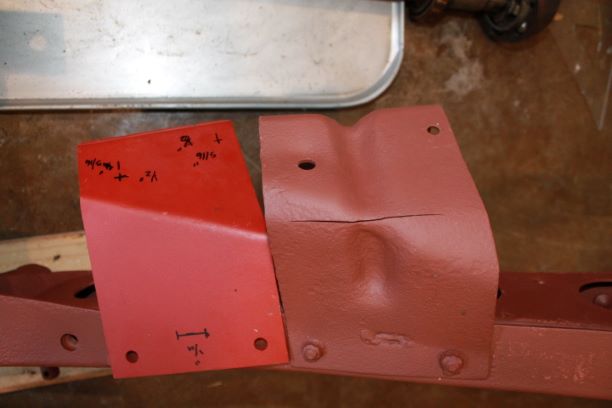
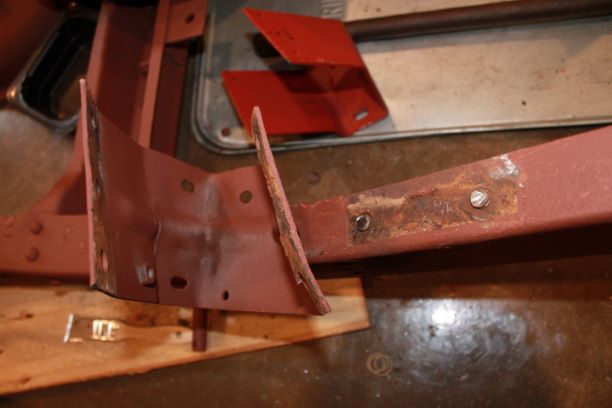
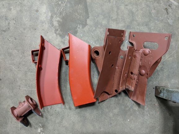
Removing the old engine brackets was not difficult. I used an angle grinder to shear off the top of the huck rivets on the top and bottom. I used a cold chisel and hammer to separate the bracket from the frame. They 'popped off' nicely. I heated the rivets in the hole with a propane torch and with a drift and hammer was able to pop those out. The remnant of the weld from the bracket was easy to grind down and then the paint and rust taken off with 80 grit wheel.
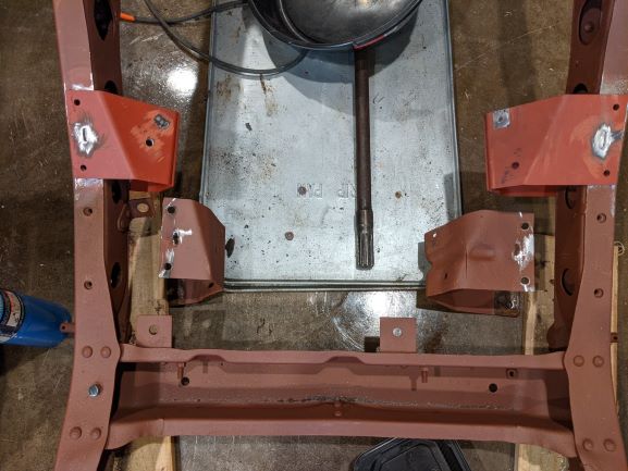
Here are the two brackets slid onto the frame. THe holes line up nicely. You can see the original brackets to the side. Again, I am not happy to have to replace them, but the fatigue, the cracks and the multiple bends is inviting problems.
Frame Repair
I had four parts of the frame that needed repair:
- Replacing the Engine brackets
- Replacing the Frame horns
- Installing a clutch pedal tube with replaceable bushings
- Repairing the scabbed frame rail repair on the passenger side
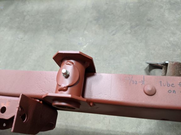
I am not an accomplished welder, and since two of these are structural and critical I elected to send these items out for repair. I am glad that I did. The work was exceptional and you can barely see where it was repaired. I will learn my welding skills on less critical parts of the restorations such as body work and move on from there. Here are some shots of the finished product.
Frame Repair Complete
I collected my frame from the welding shop and was very pleased with the work they did. Here's a summary:
- The old, bent and multi-weld repaired frame horns were cut off and the new reproduction frame horns were welded on after taking precise measurements to ensure the spring eye-to-eye distances and the longitudinal orientation were all correct.
- The 1/4" drill slots on the reproduction engine brackets were welded to the frame.
- The old clutch and brake pedal shaft housing was removed and the new one with removable bushings was welded in the same orientation.
- The two scabs that covered the steering mounting location were removed. New metal was welded in place and ground to the correct profile. The measurements for the three steering box bolts were precisely recorded and re-drilled.
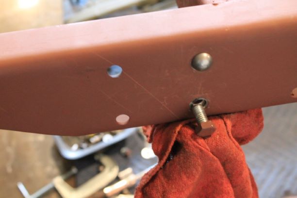
I took the time to clean things up, touch up the primer and check for any additional repairs that I could make. I elected to replace the 4 bolts that hold the rear cross member in place with the faux rivets that shear off. I also installed my fuax huck rivets on the engine brackets, peened the bolt to the nut and then ground the threaded bolt profile to look like a huck rivet.
In order to get the faux rivets installed, I used a metal clamp to hold the rounded part of the rivet tightly to the frame so that I could get the shear nut tightened down without the rivet head spinning in the hole. The rivets have splines, but they just were having a hard time gripping the somewhat elongated holes.
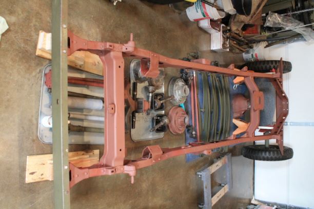
As you can see from the image on the right, I have quite a few parts lined up to begin assembly. I'm looking forward to seeing a rolling chassis soon.
Painted Frame
Assembled and refinished parts are piling up and I needed to get to the frame again. I gave it two coats of OD and let it dry in the sun. Its now back in the workshop and I began to install parts.
I had the rear axle with springs ready and alligned it with the frame for installation. I used two jack stands under the center frame stiffener. I raised them high enough so that when the front spring eyes were alligned with the hangers, the rear eyes would be fairly close to the height for installing the rear shackles. It was a bit of trial and error using a measuring tape to get it just right. This way I will not need to jack up the rear axle to the frame.
The shackle bolts slipped in fairly easily, but when the castelated nut is tightened, the hole for the cotter pin is almost too high, but bending down one wing of the pin catches the hole on one end, and the eye of the cotter pin slides in the opposite slot of the nut. i was not pleased with the finish of the bolts as one of the grease fittings threaded in properly, but the other hole was too large for the fitting. Luckily a take-off fitting threaded into the recess as it was slightly larger. I also secured the two rear spring bumpers in their location on the bottom of the frame. They came with F marked bolts and lock washers, but no nuts. They are 5/16-24.
