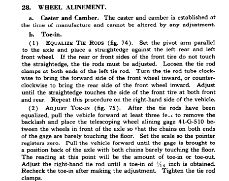
Front Axle GPW 14518
BEFORE
AFTER
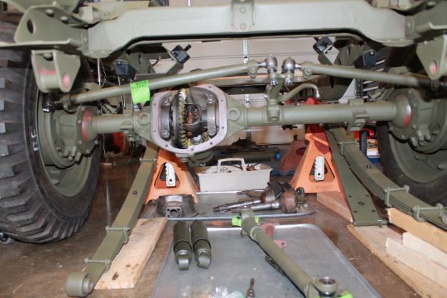
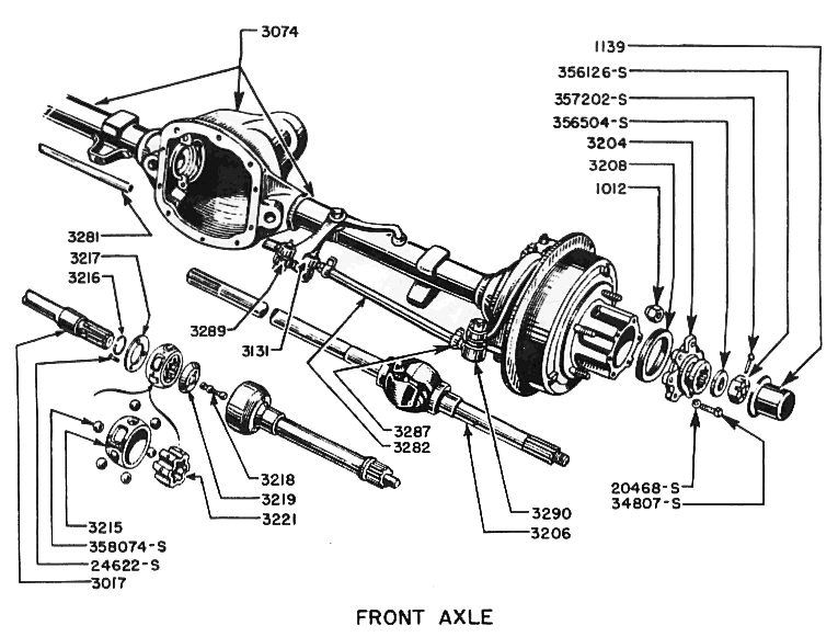
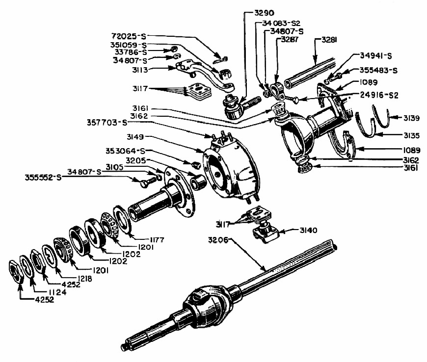
Tear Down Begins
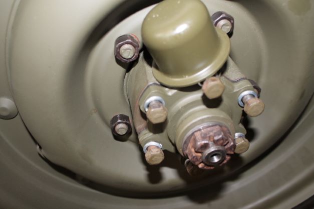
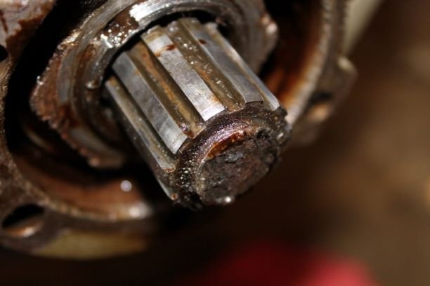
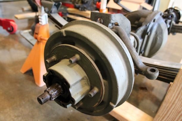
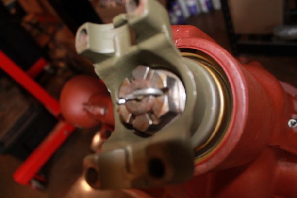
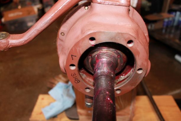
This is the reason, even with my limited knowledge of restoration, why I RARELY trust the work of others. While continuing to strip the front axle I removed the hub cap and found this.
It seems like Biff sheared the threaded end off the axle and rather than replacing it, he elected to simply cover this up with the hub. This kind of crap never ceases to amaze me. It's good for the previous owner that this was rarely driven and sat in a show room for 18 years.
Glad I didn't heed the advice of some and fire it up and drive it for a while. This coupled with the condition of the transmission make me wonder what's in the engine.
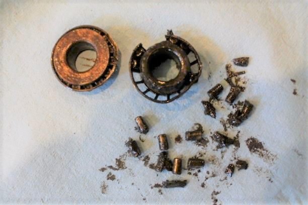
I have the axles out and everything on the driver's side stripped. The lower king pin bearing is toast. Lots of loose parts from the cage. Very ugly in there. WIll do some research as to why both bearing cages are deformed. I will need to see if these are shimmed like the dodge king pins. There are no shims at all under the steering arm or bottom pin bearing retainer.
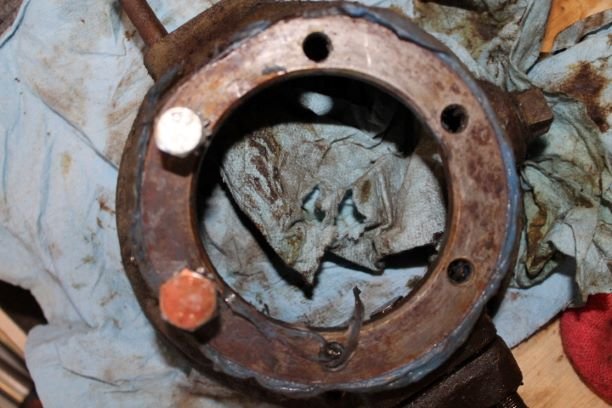
Here is another issue with the front axle. Three of the thread holes of the LS steering knuckle are over-bored with a larger thread size. I could reuse this either with the larger bolts, or helicoil it and go back original size, or I could get another.
Just one of those cost/time challenges in restorations that you can't see when you buy it, and you won't know when it's assembled. For peace of mind, I'll replace it.
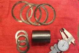
Here are the shims that were in the front axle pinion:
Inner Pinion Shims (Large)
GPW 4660C 0.010" 3 ea
GPW 4660D 0.030" 1 ea
Outer Pinion Shims (Small)
GPW 4659B 0.005" 1 ea
GPW 4659C 0.010" 2 ea
Tear Down Continues
Turning to the RS front hub and axles: Here is the before dis-assembly.
I am amazed at how folks don't tend to simple details such as putting a lock washer on all bolts. Only had two of six. Easy fix though.
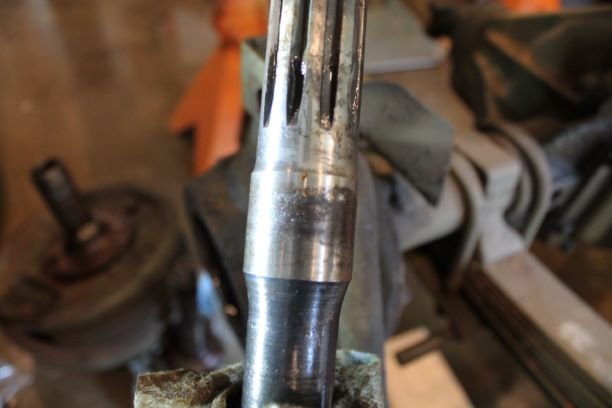
There is a lot of pitting on the bearing portion of the inner shaft. Looks like a replacement here as well. It would only be a matter of time before the friction, heat and wear would take a toll on that location.
I continued to take things apart and eventually discovered that there had been much damage to the pinion and carrier as there were missing and broken teeth and a lot of damage to the carrier. As with the rear I will be adding a new ring and pinion along with a carrier.
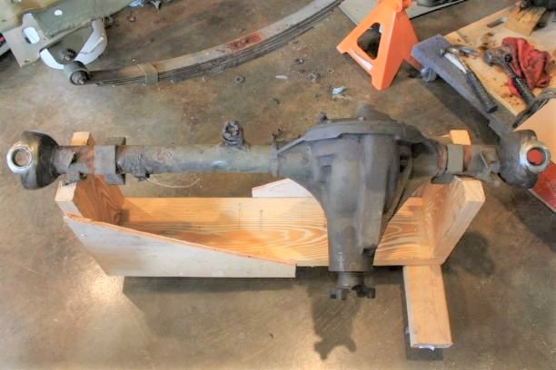
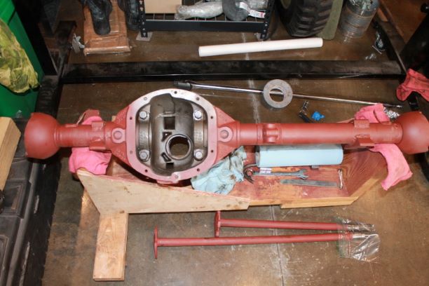
Here is the rear axle on my wooden stand ready to begin the rebuild process.
Inspection
The TM has a lot to say about Inspecting components. The axle housing is in very good condition so I will be able to reuse that. As mentioned above, I am going to start with a fresh matching set of pinion and ring gear and as with the rear axle, I'll install those with fresh bolts and lock tight, abandoning the thin retaining tabs which probably caused the problems to begin with. The carrier was also so badly damaged and possibly warped due to the "sudden stoppage" that to reuse it will only complicate matters.
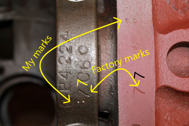
During disassembly I marked the orientation of the main bearing caps with 1 and 2 punch marks on both the cap and on the face of the machined cover surface. After cleaning everything up I noticed a set of 4 "7s" The caps had been installed in the wrong orientation albeit at least in the correct side. Here's an image of that issue. The other side has two number 7s also, but in a horizontal configuration. The cap on that side was reversed as well.
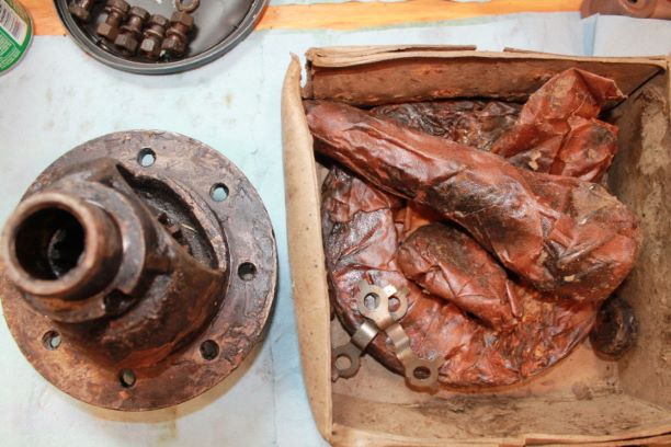
I am taking my time getting everything together, and will have to remove the 80 year old coating of wax and cosmolene that covers the new components. I'll use a hot air gun and kerosene to speed things up. That will allow me to do a further inspection of those components.
Research and Ordering Required Parts
While I am doing my research and gathering parts that are on hand, I have taken the time to take an inventory of everything that I need and get it on order BEFORE I start the assembly.
I always replace: seals, cups, bearings, gaskets, broken studs and bolts with damaged threads. I use new lock washers, new star washers and new nuts all the way around. Bolts, given the many "F" marks I try and salvage with the exception of the ring gear bolts. I understand one should neverre-use those. I ordered new grade 8 Spicer bolts.
Research has been a big help in ensuring I install parts correctly and get the right parts to begin with. The front axle has some peculiarities depending on which type of axle joints are installed. I have the RZEPPA joints and as such there are a few areas that require different bushings/seals/set up
- Outer Axle: requires a simple Axle Thrust Washer with an oil seal.
- Spindle Bushing. requires a lip-less bronze bushing.
- Shimming the axles: Install a 0.060-inch thickness
of shims between the drive flange and the hub.
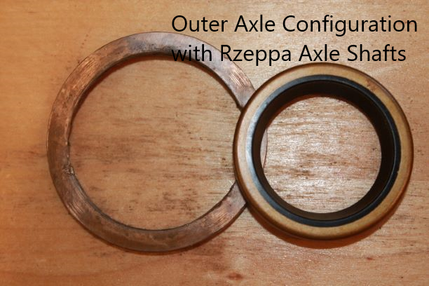
Starting the Assembly
The assembly of the front axle will be right out of the TM. I'll follow the steps in order and add images where needed. Much of the process is the same and has been documented in the rear axle page.
I thoroughly cleaned the axle shaft to make sure any grease and blasting media was removed. I use a paint roller, cut lengthwise and coiled in the tube. I push the rolled down the tube with a length of 1/2" PVC. Keep doing until the roller is clean. I cut the roller into about 3" rolls and then cut along the long end so it can be "coiled" in the tube. Use lots of cleaner. I follow up with clean rags and a heat gun.
The first thing I did was to chase all of the threads for the diff cover and the bearing caps. Next I installed the two inner axle shaft oil seals making sure the "lip" is toward the inside of the differential carrier, not the tube.
The next step is to check the steering pivot arm shaft and replace if it is worn less than 0.747". I elected to replace this part anyway.
The TM States:
(b) Pivot Arm Shaft Replacement (fig. 53). With a long nosed
drift, drive out the dowel that secures the pivot arm shaft to the axle housing. Tap the shaft out of the housing. To install a new pivot arm shaft, insert it in the bracket on the housing with the dowel slot in line with the dowel hole. Drive dowel in place.
I've already removed it so a new one will be inserted.
(c). calls for the inner pinion bearing cup to be replaced, which I will do. Since I have an entire new carrier and gear set, I am using my undersized inner pinion cup because I have to make a few adjustments to get the pinion depth and re-load correct. I will press on a new inner bearing and begin the depth setting and pre-load drill as with the rear axle, which I described in detail there.
(d) To install new bearing cups, place the bearing cup in position and tap the cup lightly until it is flush with the shoulder in the axle housing. I placed the cups in the freezer over night and used a bit of lube to allow them to slide in. I wanted to be careful not to break off the thinner outer lip of their housing, so I focused my "banging" on the edges 90 degrees to either side of the small lip. I was using a 42mm bearing/seal ring driver which just fits inside the cup recess.
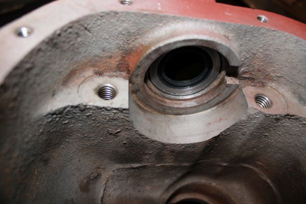
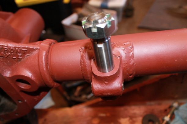
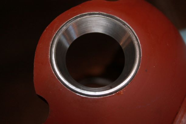
Axle Housing Outer Bushing and Seal
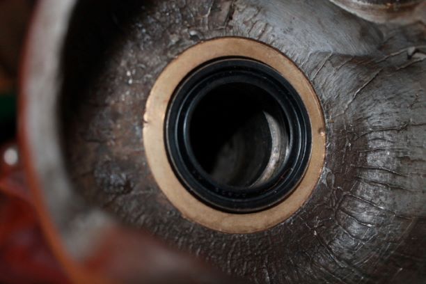
As mentioned above, I am replacing the outer axle shaft bushing. There are two types, one is used for the Tracta axle to keep it centered, and one for the Bendix and Rzeppa axles, as their universal joints are self centering. I using the flat bronze washer type as seen in the photo. That was driven in with a 57mm bearing/seal driving ring and staked in place.
The seals were easy to install. The orientation is with the lip outward not into the axle so as to keep the grease from migrating into the axle housing.
Setting the Pinion Depth
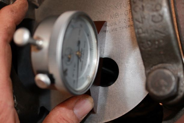
I pressed on the Inner Pinion Bearing (Timken 31953) onto the shaft in its proper orientation. I have my set-up inner cup (Timken 31520) already set in the differential with no shims added. This way I can check the correct depth and add shims as required.
Using a depth micrometer, I get the following readings for three measurements:
Reading No. 1 2 3
gauge length: 3.015" 3.015" 3.016"
(-) Needle reading: 0.354" 0.354" 0.355"
(-)Plate thickness: 0.375" 0.375" 0.375"
Pinion depth: 2.286" 2.286" 2.286"
Average depth: 2.286"
Since the pinion is deeper in the recess of the differential, I will need to raise it up by adding shims under the bearing cup. I'll add .036" worth of shims to the bottom of the cup to get the pinion to the required depth of 2.250" and then measure again. am using 4 shims at 0.008" and one at 0.004"
Reading No. 4 5 6
gauge length: 3.015" 3.015" 3.015"
(-) Needle reading: 0.394" 0.394" 0.395"
(-)Plate thickness: 0.375" 0.375" 0.375"
Pinion depth: 2.246" 2.246" 2.245"
Average depth: 2.2456"
It looks like I will need to add another 0.004 and try again.
On each of the final readings (7,8 and 9) the needle reading was 0.398: which accounts for the 0.004" difference, so with 0.040" of shims ( 5 x 0.008" shims) I have a proper pinion depth of 2.250"
Pinion Pre-load Adjustment
As outlined in the Rear Axle Section, I will adjust the pinion bearing pre-load to between 12-20 inch pounds. I will re-use my outer pinion bearing that has been honed for a slip-fit and work the shim stack to get a suitable pre-load.
I will begin with 0.060" shims and see what I get. As I tightened the pinion nut to about 45 ft/lbs, the pinion was binding heavily. I added .020" shims and tried again. After torqueing to 95 ft/lbs, the rotational force on the yoke was about 30 in/lbs. I added another 0.010" shim and ended up with 12 in/lbs or rotational force.
0.060" shims = too tight
0.080" shims = 30 in/lbs
0.090: shims = 12 in/lbs
Install Ring Gear and Carrier
I installed the ring gear on the carrier using new bolts and lock tite. I checked the fit of my set-up bearings on the carrier to make sure I would not have to use a puller each time. A bit of 320 grit on the bearings and a light clean up of the bearing surfaces on the carrier and things slid on easily.
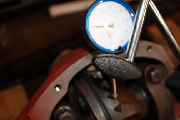
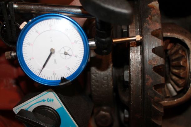
I installed the carrier in the differential and using a screw driver to pry the cones to one side I measured the gap at 0.084". Adding 0.008" IAW the TM I ended up with 0.092" shims required, using half on each side I came up with a combination of 0.045" on the ring side and 0.044" on the bolt side, a bit less than 92. I then installed the carrier, having to use a rubber mallet with a few whacks to get it to seat. The caps were secured and torqued. I then measured the backlash and ended up with 0.006", which is acceptable.
The runout on the ring gear ended up being +/- 0.0035, which is slightly above the tolerance. I will not fight this small deviation at this point.
After slipping an axle in the carrier from the knuckle side and rotating the carrier, I was not pleased with the meshing of the spider gears and the free play. I am going to take it out and re-install the ring and spider gears using different parts to see if I can improve things a bit. I will also use a stone to polish the ring-bearing surface of the carrier in an effort to remove a bit of the run out play.
After honing the carrier surface and using new spider gears and shims, I am happy with the fit of everything. I secured the new Spicer bolts with lock tite and installed the carrier in the differential and torqued it down again. I used the same shim configuration as discussed above and ended up with the following results:
Backlash: 0.004"
Runout: 0.003 +/-
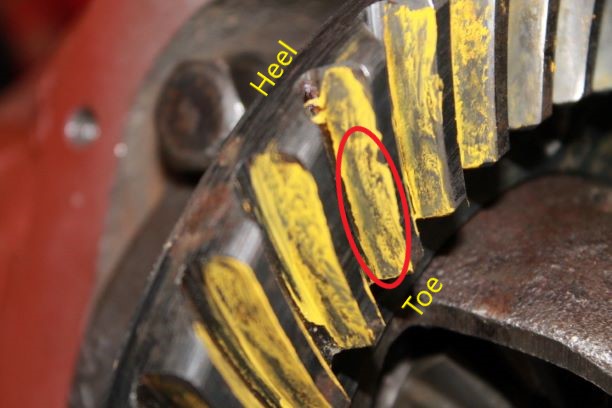
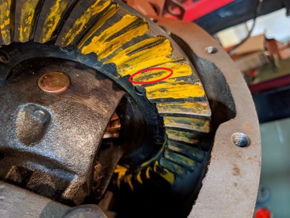
The back lash is supposed to be no less than 0.005" and the TM states to move the ring gear away from the pinion by the amount equal to the desired change. Since I do not have that small of a shim, it will be difficult to make the adjustment. I suppose I could wicker a different combination of shims to do so, but I'm not fussing over 0.001". Gear mesh pattern as shown in photo is a blend of Ideal to Competition, so I am happy with this. Now I will re-install the cap bolts using thread sealer and torque them to spec..
Cleaning and Inspecting Rzeppa Axles
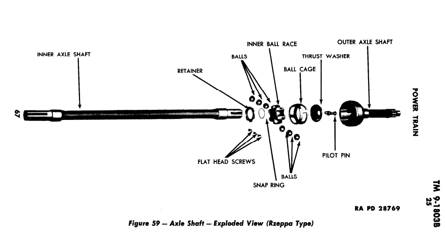
From the TM:
1) RZEPPA UNIVERSAL JOINT.
(a) Remove Inner Axle Shaft (fig. 59). Remove the three flat
head screws that secure the retainer to the inner ball race. Slide the inner axle shaft out of the universal joint. Remove the pilot pin from the outer axle shaft If the pilot pin does not drop out of the outer axle shaft, hold the shaft upside down and tap the shaft on a piece of wood.
(b) Remove Balls From Cage. Tilt the cage in the
axle shaft cup until the opposite side of the cage is out of the housing. It may be necessary to use a brass drift and hammer to tilt the cage. Use a screwdriver to pry the steel ball out of the cage. Repeat this operation until all the balls are removed.
(c) Remove Cage and Inner Race From Axle Shaft (fig. 40).
Turn the cage in the axle shaft cup in line with the shaft and with
the two larger elongated holes between two bosses in the shaft. Lift the cage and inner race from the axle shaft cup.
(d) Remove Inner Race From Cage (fig. 41). Turn the inner
race in the cage so that one of the bosses on the inner race can be dropped into one of the two elongated holes in the cage. Remove the inner race from the cage.
I'll take some pictures of the assembly process as the parts will not be full of dark grease. Removing the 3 flat head screws is not easy. All of them were punch set so that they would not move with a screw driver. I tried a screw extracotr and that was problematic as you cannot get the extractor completely vertical with the screw because the drill impinges on the axle shaft. In the end I ruined the retainer. I have a rebuild kit but was hoping not to have to use the parts. I ordered some 8-32 x 7/16" hex cap screws to replace the old ones. I will install them with lock-tite rather than pucnching the edges.
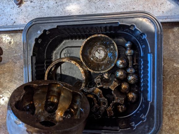
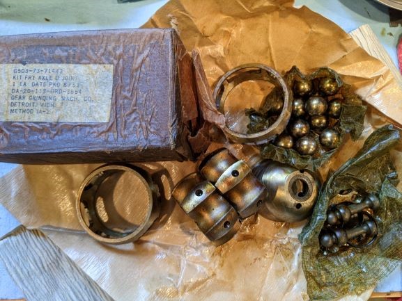
Details and Inventory
Before progressing on the front axle I rounded up all of the needed parts. Spindles, hubs, hub caps, brake plates, wheel drums, hub bolts, brake plate bolts and nuts, hub bolts brake line guard, seals, studs and anything else. Its a lot of parts. I will use all new star and lock washers and nuts for the brake backing plates. I chased the threads on the drums, placed a new bushing in the spindle, and put all of the bolts in a tub to degrease and prepare for cleaning.
These tasks are all time consuming, but will make life easier when assembly begins. Normally I clean a part as I need it, but that interrupts the flow of work. In this case several hors of this menial unrewarding work makes things smoother later.
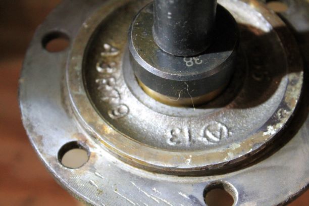
Rzeppa Front Axle Assembly
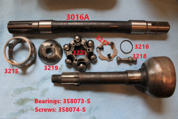
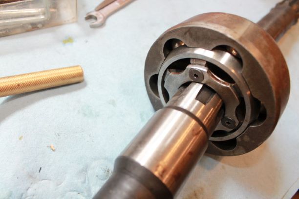
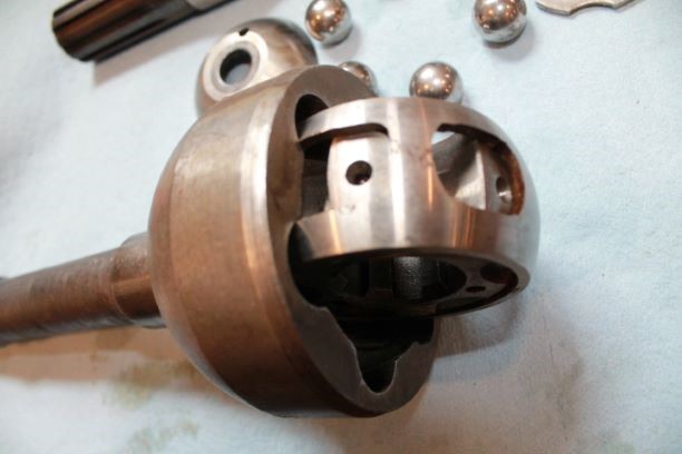
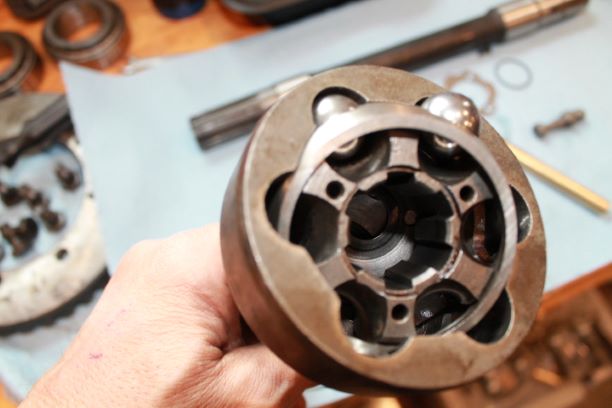
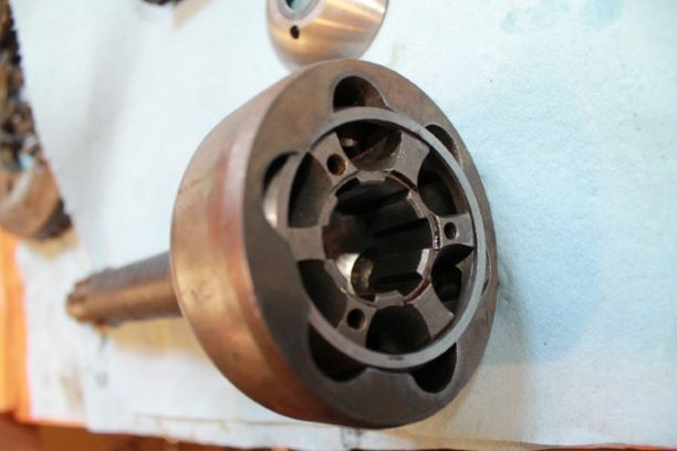
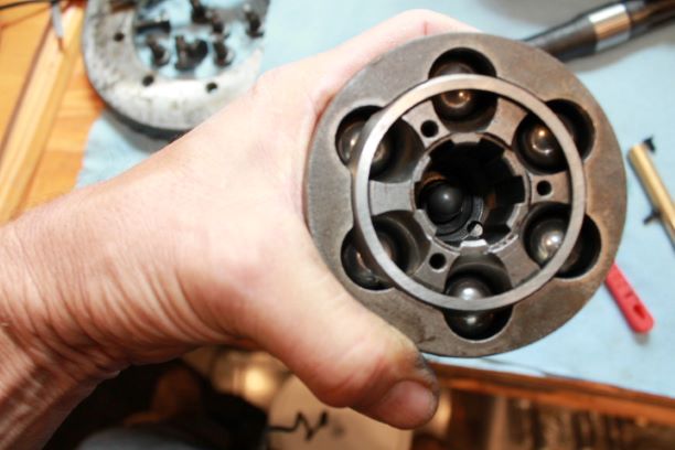
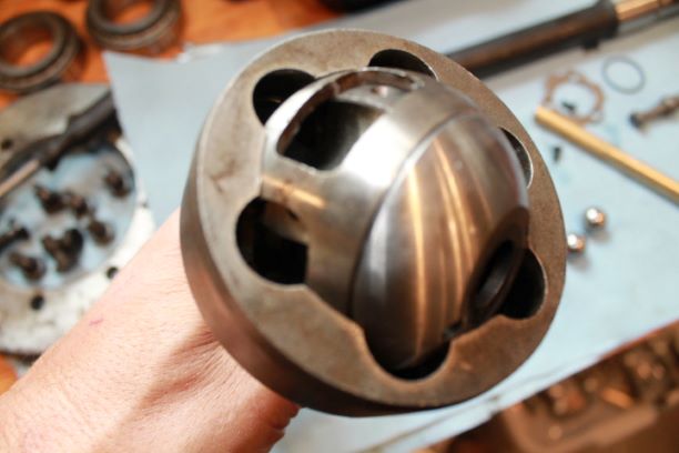
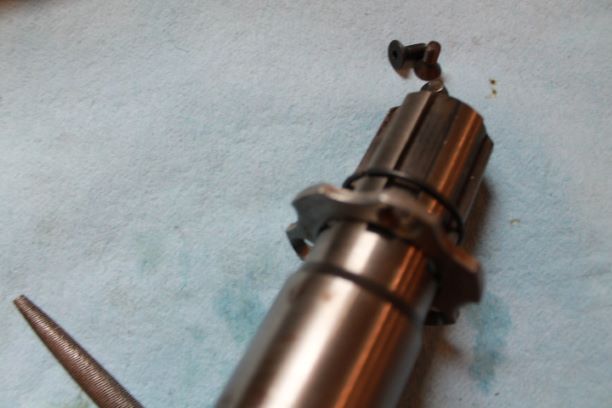
Referring to the parts diagram as needed I assembled the front axle joint in the reverse order of the TM as outlined in disassembly. The numbers match the smaller pictures at the bottom, going left to right, top to bottom.
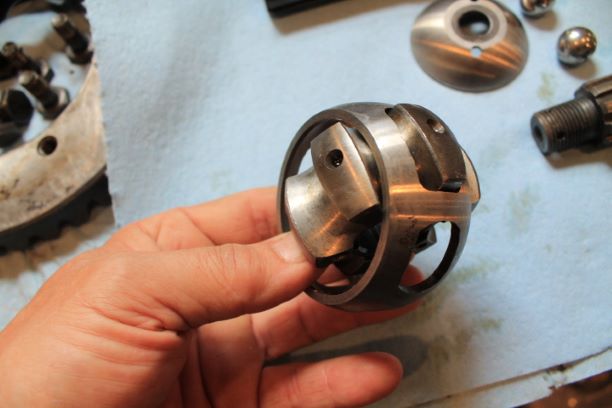
- Install inner race 3221 into the cage 3215 by inserting one of the lobes into the elongated slot in the cage. Now you can tilt it in, lower it a bit and rotate it into the cage.
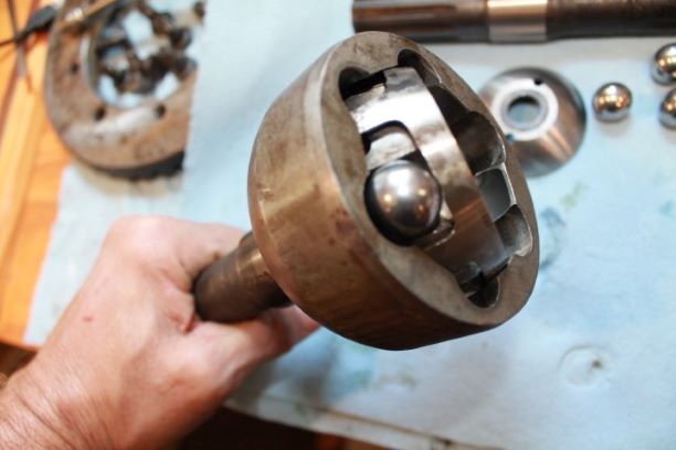
- Insert cage and inner race into joint. Using the two elongated holes in the cage, slide them onto two opposite lobes of the joint and down into the recess. You may need to gently file the cage openings slightly to remove any burs or sharp edges. A light hit with a rubber mallet seats it into place. (If it is sticking do not force it. just be patient).
- Rotate the cage and race so that the recessed edge on the inside where the axle goes is on top. It is the only side that the small screws will thread in.
- The TM does not mention the cupped thrust washer 3219. Insert it by by rotating the cage sideways until you can slide it into position. It will end up at the bottom of the assembly.
- Add balls into the cage slots by tilting the cage so that you can add the balls from the top.
- It gets easier as you fiddle with it and figure out how the method works.
- Install the pilot pin 3218 with the flat into the hole so that the ball shape is showing. The ball fits into the recess of the axle.
- Install the retainer 3217 onto the axle with the beveled edges for the screws pointing upward. Slip the snap ring onto the splines and into its groove. The axle can be slipped into the outer axle shaft and the screws secured. I elected to use screws with hex heads for easier tightening. I secured them tightly and used lock tite.
- All that remains is to grease the assembly with NLGI-2
Front Axle Parts Preparation
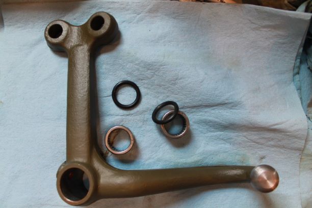
The continued work of getting all of the components ready for the front axle continues. I have the steering arm ready and painted. I pressed in the two bearings and inserted the rubber grease seals. I made sure there is space between the two bearings for the grease fitting opening so that it is not closed off. If you press the bearings in too deep, once could close off the grease cavity. The bearings are seated below the surface of the arm just enough to allow the seals to sit flush.
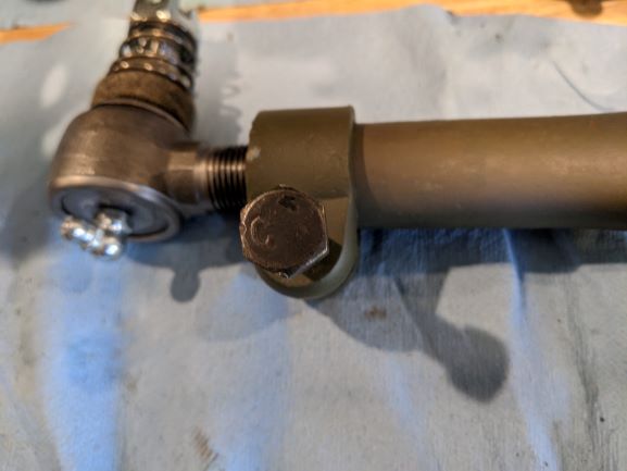
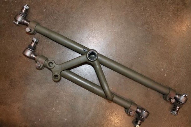
The two tie rods take a lot of work. Mine were very rusted inside and a great effort was needed to remove the tie rod ends. Heat and slow back and forth work succeeded. There are a lot of little details in getting these set up right.
- Chase the ends. One is RH thread, the other is LH thread.
- Use anti seize on the threads so they do not rust shut
- Install a RH end on one side, and a LH thread on the other.
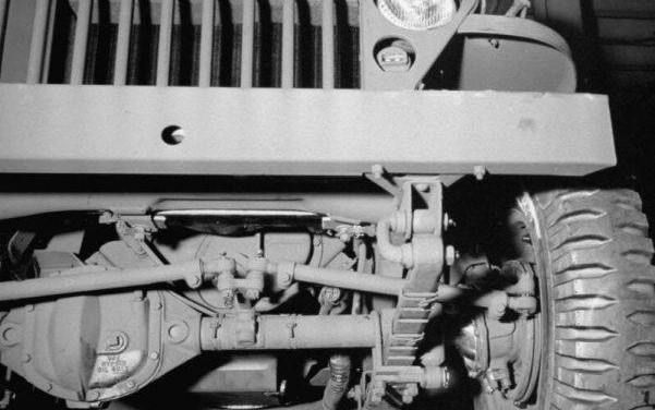
- One end points up the other points down. The factory image shows the proper orientation.
- The clamps should be installed so that the opening is aligned with the longer slot on the tube and the bolts on the bottom.
- Grease fittings should be installed all facing forward for ease of maintenance
- Use the same orientation of the threads on the ends; LH thread on the Left of each tube and RH thread on the Right for both tubes. That way when you rotate the tube to shorten or lengthen the tubes, both tubes change in the same direction.
- I found on a site that the initial length of set up from the center of the grease fitting to the other grease fitting should be as follows:
Long Tube, 24 1/4", Short Tube 17 11/32"
That leaves about 4-5 threads showing on each end. I could find no reference i the TM to this, so I'll give it a try.
Spider Gear Problems
After doing all the work on the settings and pattern for the differential I installed one of the Rzeppa shafts to check fit and see how things were progressing. When turngin the axle there was a severe clacking sound in the differential, caused by the spider gears. It took me a while to find the proble, thinking it was the spider gear thrust washers and after trying different combinations I measured the inside diameter of the axle gear recess. They were 0.015" greater than the outer diameter of the gears. That allowed the gears to essentially "wallow" in these recesses and caused the noise. If I had not found this until later it would have been much more work to get it right.
This was supposedly a NOS carrier, so I contacted the seller and he sent me another which after cleaning up measured correctly. The assembly went quick, and after a few adjustments to the carrier shims I ended up with 0.040' on the bolt side, and 0.032" on the ring gear side. The run out was great at 0.001" and the backlash a bit tight at 0.004" It should be 0.005" minimum. I will check again after installing the new bearings and pinion cone, removing the set-up ones.
Finishing the Differential
I replaced the set-up bearings and cones with brand new bearings and cones. The rear pinion nut torqued down nicely with the set up yoke and gave me about 22in/lbs of resistance before installing the oil seal. I installed the oil slinger and used a bit of RTV on the seal and seated that home. I have an F marked NOS dust shield to install on the yoke and then retorque everything back to specs.
The carrier has new bearings and cones and was installed without issue. I used some thread sealer on the cap bolts as they are open to the rear of the carrier. Run out and backlash did not change. The Differential is ready to be buttoned up as soon as I get the knuckles adjusted and the axles installed and working properly. Fo now I'll leave it open just in case and be mindful not to drop anything in the housing.
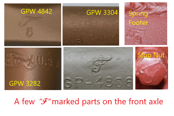
As I assembled everything I took some shots of some of the F marked parts. Its nice to see them all coming together.
Starting in the upper left corner and proceeding closkwise:
Yoke
Drag Link
Axle Spring Pad
Tie Rod
Shaft Coupling Yoke (Rear Axle)
Steering Knuckle Stop Bolt
Pivot Arm and Steering Knuckles
From the TM:
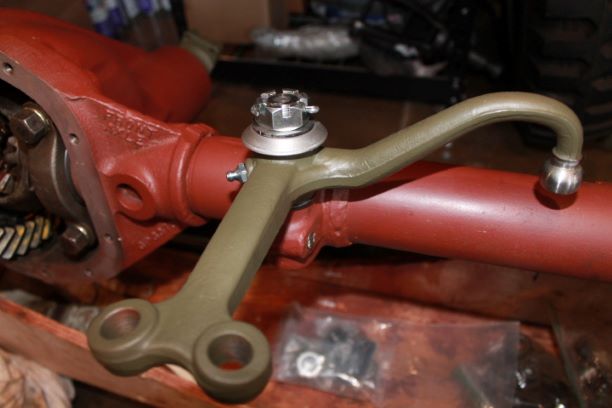
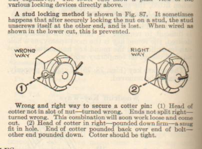
m. Install Pivot Arm (fig. 46). Insert the two rubber seals in the pivot arm. Place the flat washer on the pivot arm shaft. Place the pivot arm on the shaft with the ball joint of the arm facing downward. Place the flat washer and dust shield on the shaft. Ir, stall the castellated nut and cotter pin.
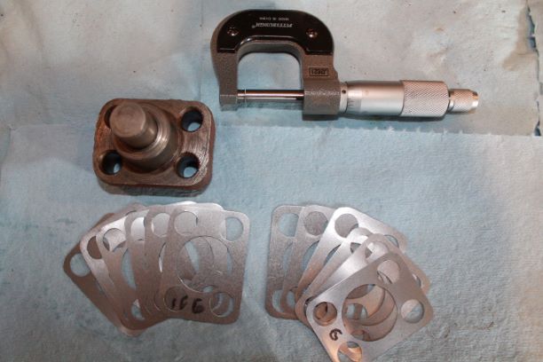
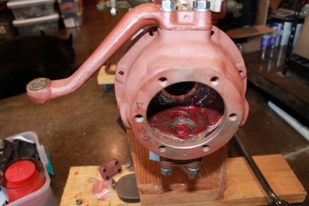
n. Install Spindle Housing (fig. 76). Dip the two spindle housing bearings in grease. Place the bearings in the bearing cups axle housing. Place the spindle housing on the axle housing with the grease plug to the rear of the vehicle. Install shims totaling 0.048 inch thick on the spindle bearing cap and the spindle arm. Shims are available in thicknesses of 0.003 inch, 0.005 inch, 0.010 inch and 0.030 inch. Install one of each size on the top and bottom of the spindle housing. Place the lower bearing cap on the spindle housing and install the four nuts that secure the cap to the spindle housing. Place the spindle arm on the spindle housing and install the four nuts that secure the spindle arm to the spindle housing.
The process was fairly simple. The shim pack I had included only 0.006" shims. I used a recommended procedure of starting with all the shims under the lower spindle bearing cap, so it received 12 shims for a total of 0.096".
o. Adjust Spindle Housing (fig. 72). Check the tension of the spindle housing by hooking a scale to the end of the spindle arm. The tension should not be more than 6 pounds or less than 4 pounds. If the tension is over 6 pounds, shims must be removed from the spindle housing. If the tension is less than 4 pounds, shims must be added. When removing or adding shims, be sure the same thickness is removed from, or added to, both ends of the spindle housing. Remove, or add, shims until the correct tension is obtained.
There was upper play in the arm which I measured at 0.008", so before torqueing I removed two shims. Here are the results.
- 0.096" (12shims) up and down play
- 0.080" (10 shims) 0.07 lbs drag
- 0.064" (8 shims) 1.58 lbs drag
- 0.048" (6 shims) 2.50 lbs drag
- 0.042: (5 shims) 5.74 lbs drag
At this point I placed three shims under the top cap and two under the bottom AND checked the torque at 50 ft/lbs. At this point I achieved between 7.25 lbs of drag. The final torque setting gave me the added drag. The TM states 4-6 lbs and post war and CJ manuals recommend 12-16. I am between those two settings. Rather than filling the knuckle completely with grease accomplishing nothing, I smeared a thin coating on the inside of the steering knuckles surface to prevent rust. Before installing the final 5 shims, I re-greased the bearings, just to make sure they were full..
Spindle Housing Oil Seal
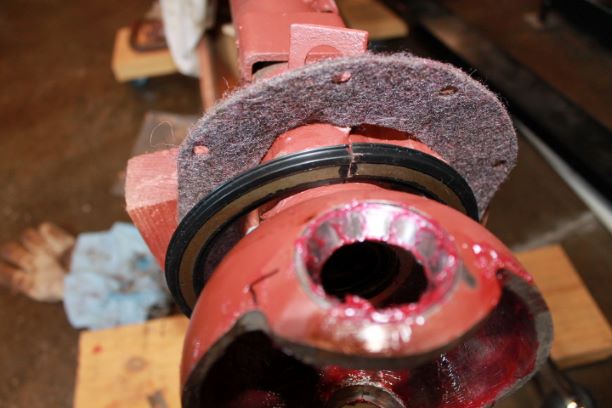
p. Install Spindle Housing Oil Seal. Place a new gasket
on the spindle housing. Place the upper and lower halves of the oil
seal on the spindle housing. Install the four cap screws that secure
the lower half of the oil seal to the spindle housing. Place the axle shaft identification tag on the upper half of the oil seal. Install the
four cap screws that secure the upper half of the oil seal to the
spindle housing.
I am using RFJP knuckle oil "Dust" seals. They go on fairly easily. One hint from another restorer is to press grease, by hand, into the felt seal. This allows it to be slipped over the knuckle before final assembly, and it provides a level of water repellant to the felt. This way I did not have to cut the felt. Install these before your final shim placement and torque of the caps as shown above. I am awaiting a set of Rzeppa Joint tags, so I will not torque the nuts to final 15-20 ft/lbs.
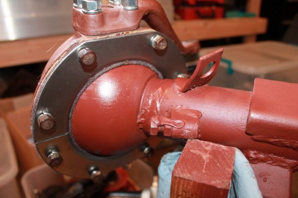
Finishing the Axle
q. Assemble Axle Shafts. Done in detail posted above.
r. Install Axle Shaft. BENDIX AND RZEPPA JOINTS. Slide the axle shaft in the axle housing. It will be necessary to turn the axle shaft until the splines on the axle shaft are in line with the axle shaft gear in the differential. Done, see image at right. Just be careful and do not damage the rubber oil seals with the splines and do not forget to heavily grease the joint.
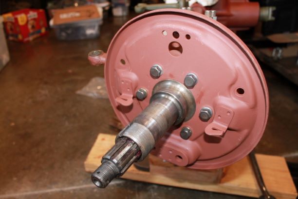
s. Install Brake Plate and Spindle. Place the spindle on the spindle housing. Place the brake plate on the spindle with the wheel cylinder toward the top of the brake plate. Line up the holes in the brake plate and spindle with the spindle housing. Install the six cap screws that secure them to the spindle housing. Done, see image at right. Bolts torqued to 35 ft/lbs with split lock washers per TM.
t. Install Hydraulic Brake Hose (fig. 46). Install the brake hose
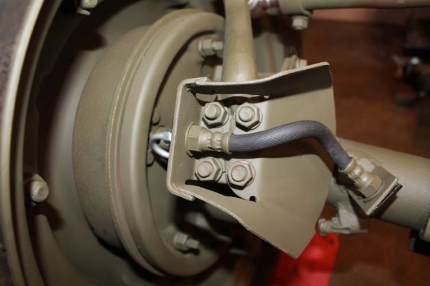
to the brake line on the axle housing. Install the clamp to the brake hose at the bracket on the axle housing. Insert the brake hose through the guard and connect the hose to the brake line on the brake plate. Install the brake hose clamp at the guard. Done, see image at right.
u. Install Hub and Brake Drum (fig. 46). Pack the wheel bearings with the specified lubricant. Insert the hub and brake drum on
the spindle with the inner wheel bearing and grease retainer in the hub. Insert the smaller thrust washer on the spindle and install the bearing adjusting nut. Tighten the adjusting nut until the brake drum binds when turned; then back off the adjusting nut one-eighth turn. This will give the correct wheel bearing adjustment. Install the lock washer and lock nut on the spindle. Bend the ears of the lock washer over the lock nut. Done, refer to Wheel Section for images.
v. Install Drive Flange. RZEPPA TYPE AXLE SHAFTS. Install a 0.060-inch thickness of shims between the drive flange and the hub. Place the drive flange on the axle shaft. Install the six cap screws that secure the drive flange to the hub. Install the castellated nut on the axle shaft. Install the hub cap on the drive flange.
w Install Tie Rods. Insert the ends of the tie rods in the spindle arms and pivot arm. Be sure the dust shield and felt washer are on the tie rod ends. Install the castellated nuts that secure the tie rod ends to the spindle arms and to the pivot arm. Torque them to 40ft/lbs
Rzeppa and Ratio Tags
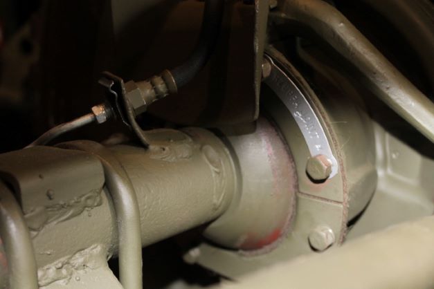
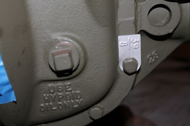
After having been on back order for nearly 2 months the Rzeppa and Differential Gear Ratio Tags finally arrived. I wanted to install them as I assembled the axles, but I thankfully elected to wait so I could get my frame off the ground.
The Rzeppa tags were a bit tedious to install on the front knuckles due to the brake line shield being in the way of the upper bolt. It just took a bit of time. I could not find a definitive answer on whether they are supposed to be mounted at the 1-3 o'clock or the 9-11 o'clock position. I went with the former following an image of the much acclaimed Alasdair Brass GPW restoration images on Jeepdraw.
Final Details and Alignment
I finally finished the last details for the front axle. With the Rzeppa axle joints, the TM states that the shims should be 0.060" thick. There is no adjusting. I selected 2 x 0.030" shims for each side, installed the bolts with lock washers and the flange and torqued them down to 45-50 lbs.
The axle nut does not have a specification, only to secure it tightly and install the cotter pin. The hub cap is then installed using a rubber mallet.
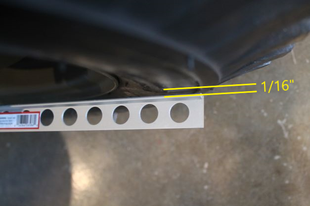
All that remains is to seal and tighten the drain plug and fill the axles. I also have to grease the fittings on the tie rod ends and bell crank and adjust toe out. I'll report that probably in the steering section after the steering box is rebuilt and installed.
