GPW 14518 Body
GPW Body Mounting Hardware
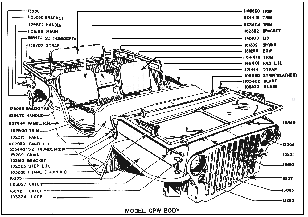
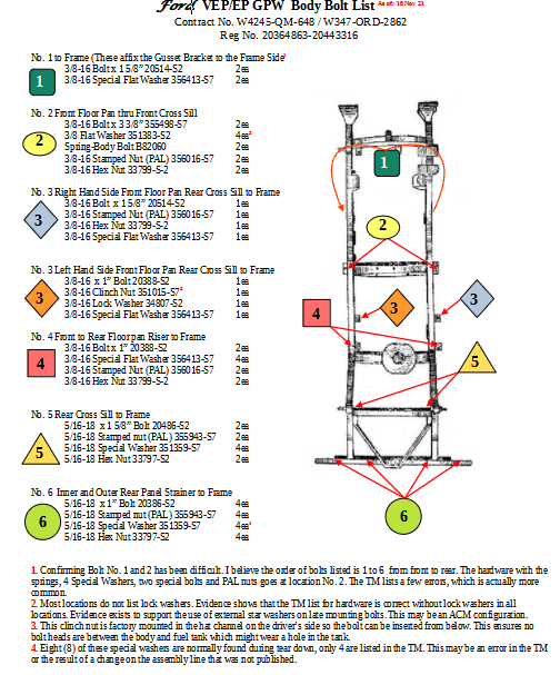
It took me a while to track down what is appropriate with regards to the hardware that is used to mount the GPW body to the frame. I started with the April 1943 TM 10-1348 and made a list of the hardware and then researched where each bolt and nut goes. This is the result of that reasearch. On the left is a schematic and a list from the TM of the hardware required to affix the body to the frame.
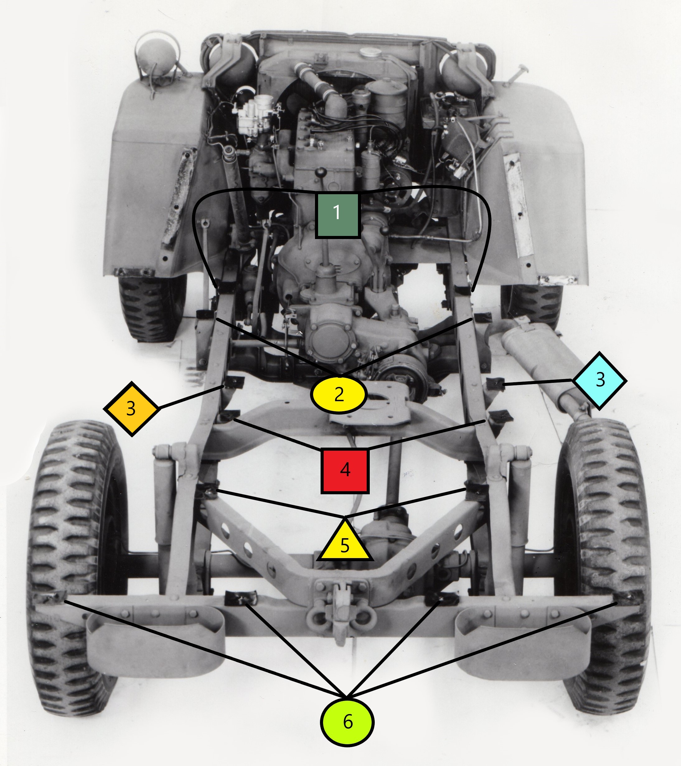
The image below shows the locations more precicely on the Ford image which has the rubber cushions or pads placed over the appropriate mounting locations.
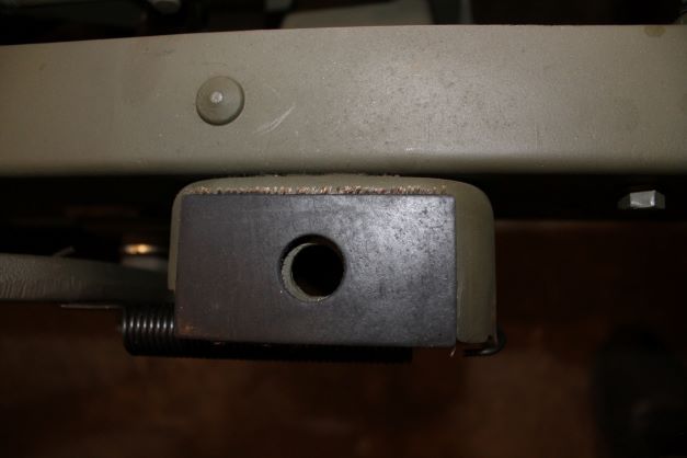
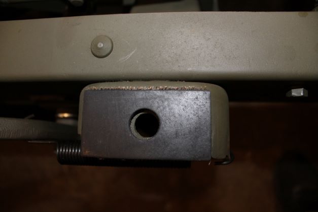
Below right is a photo of one of the RFJP reproduction pads mounted on one of the 14 locations. I used a dab of gasket sealer underneath to prvent them from moving so easily when the tub is set in place.
A Decent Tub
I was fortunate enough to have acquired a tub that was nearly restored. It appears to be an original GPW tub with a replaced floor and some work done to the front quarter panels. I am excited to get the GPW on the road, so I will focus on the big issues and get it mounted onto the rolling chassis. Here is what I will work on
- Wiring Harness
- Gauge installation
- Fuel line installation
- Ensure all mounting holes are properly located and drilled
- Mount the tub to the frame
- Attach the details
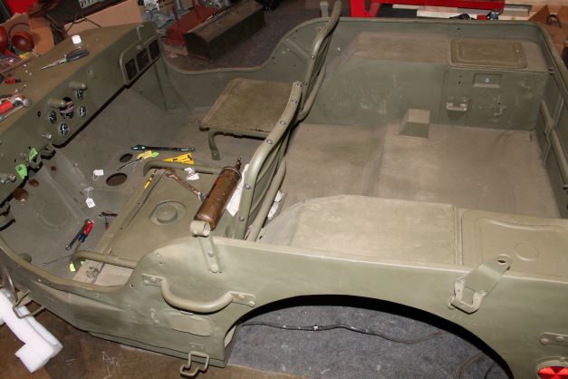
Underside of the Tub
The tub overall is in fairly good shape as mentioned earlier the bottom floor panels appear to be replaced, probably with MDJ replacements. The lower panels have no holes drilled for mounting but the single capture nut under the fuel tank is available.
I placed the tub on the frame using the four rear mounting brackets and the single capture nut as a guide, and then drilled the remaining holes through the tob floor. I put the body to frame pads in place, set the tub onto the frame and secured the four rear bolts and the one under the tank and then proceeded carefully to drill.
I am slso going to leave the steering column aff when doing this so I don't have to fight the column alignment while working the tub down onto the frame.
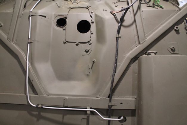
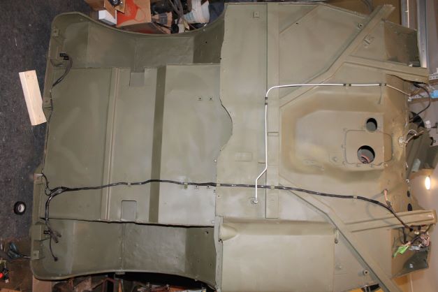
Tub Frame Mounting
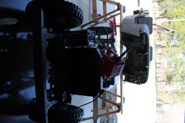
Working alone I tend to spend a lot of time figuring out how to do things by myself. In this case, I avoided the "get 4 friends to lift your tub up" routine and did it by myself. NOTE: You cannot do this with the steering column attached. I'll slide this into place from the front after assembly.Here is the methodology
ITEMS NEEDED:
- 4 sturdy saw horses or suitable stands that are higher than the height of the engine on the frame
- 2 2 x 6 of at least 8" length
- Engine hoist or cherry picker
- Cargo strap
- 2 furniture trucks to roll the body around.
PROCEEDURE:
- BE CAREFUL> By yourself the horses could shift and the tub could fall on your foot or worse. Not for the faint of heart.
- Set the body on the furniture trucks and roll it to the location behind the frame on flat ground. Make sure all your body to frame pads are in place so they won't slide off.
- Position the hoist behind the tub, connect the cargo strap and lift the tub above the level of the saw horses so you can slide one 2x6 under the rear of the tub so that it rests on the board supported by the saw horses. The legs of the saw horses must be at east 58" apart so the wheels will fit between the legs when you roll the frame under the tub.
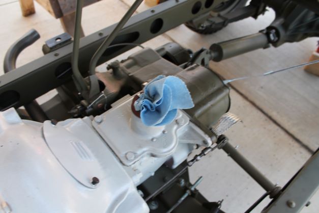
- Move the hoist to the front and repeat the same procedure with the front of the tub. Make sure the front board will not interfere with the 4WD shifters as it is lowered down. I also removed the shifter cane from the transmission.
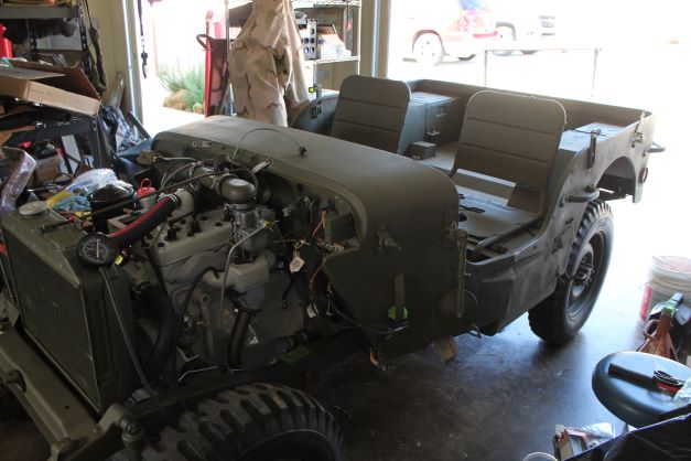
- You now have the tub fully supported above the frame and engine.
- Slowly roll the frame under the tub so that the rear frame is under the rear lip of the tub.
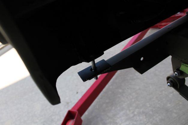
- Insert two long bolts into the rear outer tub to frame mounting tabs pointing down. You will guide these into the holes in the frame and they will act as a secure pivot point for the rest of the operation
- Place the hoist at the rear again and connect as previously making sure the lift point is centered at the back of the tub.
- Lift the tub slightly and remove the board and two saw horses.
- Slowly lower the tub while guiding the two bolts into their respective holes. The pad should be between the tub and frame. Your tub is now 1/2 secure and should not slide.
- Move the hoist to the front and repeat the process at the front. You will need to be careful to guide the tub around the shifters into their respective opening. Check all lines and cables at the firewall are out of the way and take your time.
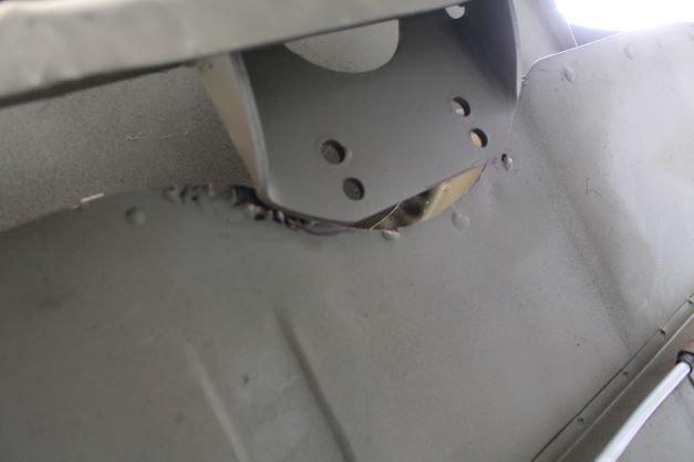
You may need to do some adjusting as I did. My new floor pan interfered with the machine gun mounting pad so I had to lift and cut off a small edge on the tub floor lip.
Front Body Gusset Bracket
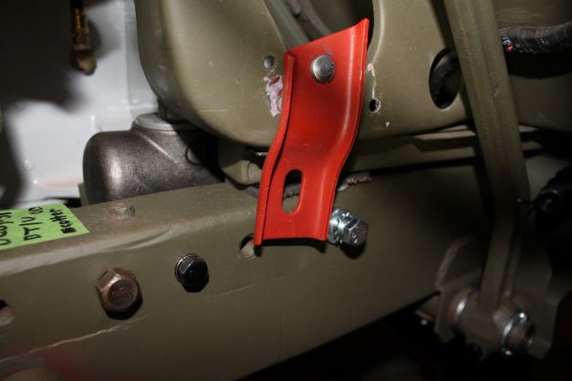
On the front of the body there are two gussets that have a bracket that is riveted to the gusset and bolted to the side of the frame. Mine had no brackets, so I ordered some. Unfortunately I forgot to install them until after the frame was bolted down. I fashioned two "rivets" from carriage bolts, modified the rivet hole and will bolt them to the gusset. This will allow me to install them without moving the body.
I ground the carriage bolts down to look like rivets, or close to them and modified the rivet hole in the bracket into a square hole. The carriage bolt fits therein and will be secured to the gusset with a lock washer and nut. Problem solved. I filled the ends of the carriage bolt with JB Weld and will file them to match.
Here is an image of the reproduction bracket with the carriage bolt installed. Its just hanging on the gusset to let the JBW dry, but when installed with fit over the rivet hole in the gusset and get bolted to the frame with hte hardware shown. The final installation is shown below under Bolt No. 2.
Installing the Steering Column
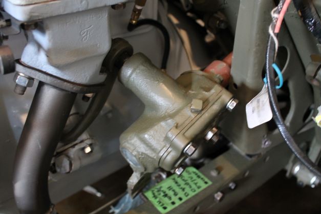
I had mentioned earlier that I did not install the steering column since I was going to install the tub to the frame by myself. I figured I would not be able to easily manuever the tub over the top of the shaft and down onto the frame alone. I hoped that without the tube on I would be able to insert it from the front of the tub beside the engine.
I just verified that it will slide in with some rotating and minor jockeying. I am glad this is the case. I will finish the steering box rebuild, insert it and secure it and then install the tube. That will be detailed in the steering section. In the image, nothing is connected, I just wanted to see if it would maneuver its way into the hole (so to speak).
Body Mounting Bolts
The tub overall is in fairly good shape; as mentioned the bottom floor panels appear to be replaced, probably with MDJ replacements. The lower panels have no holes drilled for mounting but the single capture nut under the fuel tank is available.
I will place the tub on the frame using the four rear mounting brackets and the single capture nut as a guide, and then drill the remaining holes through the tob floor. I put the body to frame pads in place, set the tub onto the frame and secure the four rear bolts and the one under the tank and then proceed carefully to drill.
I am also going to leave the steering column off when doing this so I don't have to fight the column alignment while working the tub down onto the frame.
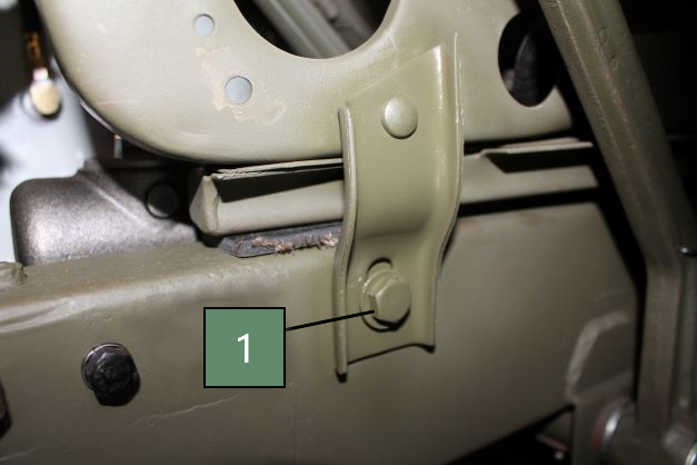
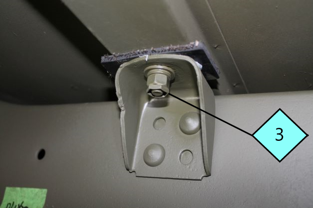
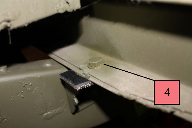
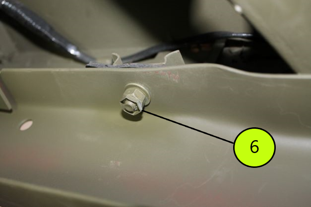
Here are images of all of the body mounting bolts pictured as identified in the drawing above.
Bolt No. 1 (2 ea) mounts the gusset bracket to the side of the frame. I added a 3/8-16 bolt a star lock washer and a special washer.
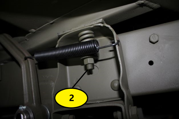
Bolt No. 2 mounts the front tub to the brackets for the transmission cross member and uses the long special bolts, the springs, 2 special washers ber bolt, a hex nut and PAL nut.
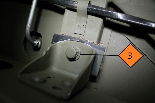
Bolt No. 3 (Right) has (1ea) 3/8-16 x 1 5/8: bolt, a special washer a hex nut and a PAL nut. Many have reported that another special washer should be placed under the bolt head in the tub, which I did. This may be a change from the early TM.
Bolt No 3 (Left) consists of (1ea) 3/8-16 x 1" bolt, a special flat washer and a lock washer. This bolt is inserted from below into the clinch nut that is factory installed in the hat channel below the fuel tank.
Bolt No. 4 (2ea) goes through the lip of the rear floor pan and has a 3/6-16 x 1" bolt, two special washers a nut and a PAL nut. These are visible from the rear wheel wells.
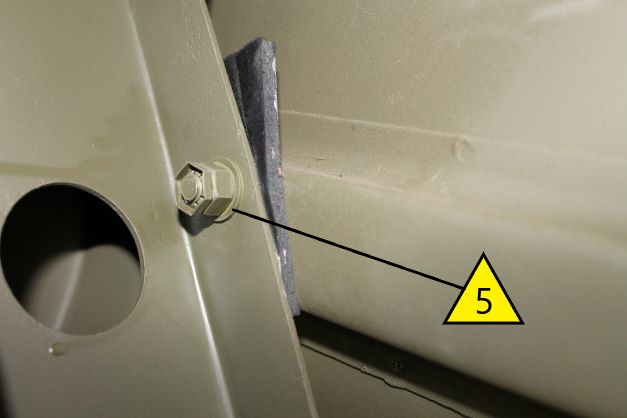
Bolt No. 5 (2ea) The kit I purchased consisted of 5/16 carriage bolts. I suppose that makes sense having a round surface in the tub rather than a bolt head to catch on boots. I'm going to leave this as is and not worry about it for now.
Bolt No. 6 (4ea) has 5/16-18 x 1" bolts that onnect the rear of the tub to the rear frame stiffener. They are installed with 4 special washers (Evidence indicates there should be 8 of these, one above nut and one below the bolt head), a 5/16 nut and a PAL nut. There are 4 of these on the back body.
Firewall Overview
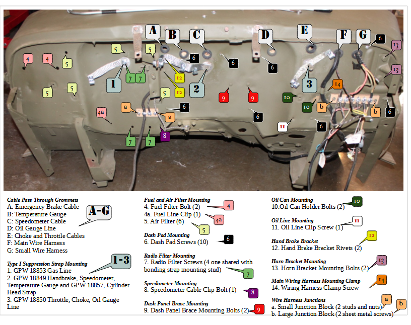
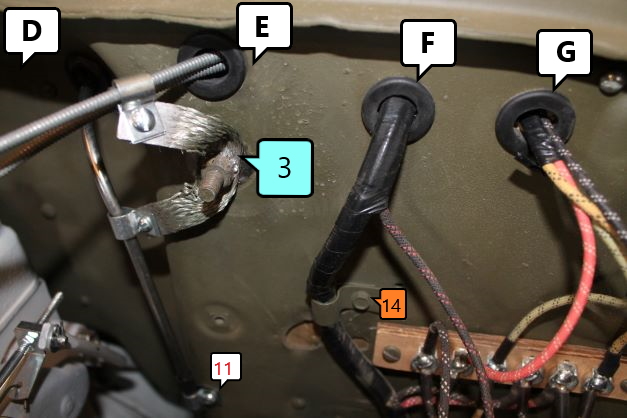
There are a lot of details at the front of the tub. The firewall has lots of attachment points and holes. Here is a diagram I created to sort ou the mess.
- Large Letters (A-G) in White box are the grommets that house the items listed in the chart
- Numbers (1-3) in light blue boxes are the bonding strap locations
- small letters (a, b) in tan boxes are for the wire harness junction blocks
- small numbers (4-14) in the various colors are for all other bolts and screws as annotated in the chart to the right
Firewall Details
Here are the details of the items attached to and passing through the firewall.
A: Emergency Brake Cable: This slides through grommet A and is clamped onto the driver's side air cleaner bracket using one of the special cable clamps, bolt, washer and nut. THere is also a grounding clamp which grounds the cable to the firewall via strap No. 2. Then it is routed under the transfer case, between it and the skid plate to the emergency brake linkage. THere is another special clamp that secures the cable to the back of the rear TC housing. The cable end is secured to the pawl using a pin and cottor pin.
B: Temperature Gauge lead is simply routed through the grommet, is grounded on the grounding strap that is secured to Point No. 2 and then into the egine block.
C. The Speedometer cable is routed from the speedometer, through the grommet and into the side frame rail and out to the connection boss on the TC. It is secured to the firewall via a screw at point No. 8
D: Oil Gauge Line. Slip the oil gauge dash clip and the bonding strap clip over the oil line and then through the grommet from the engine side. Connect the Oil Line to the gauge, secure the gauge and then tighten down the two clips.
E: Choke and Throttle Cable: Dont Cut unitl you verify and leave extra inner wire for final connection! The Choke knob attaches to the left of the ignition switch and the Throttle to the right. The Choke has 7" of shileding on the engine side and 11" of shielding on the dash side with 3" of extra inner wire sticking out of the end for a total length of 21" The throttle has 7 1/2" of extra shielding on the engine side, 11" on the dash side and 5 1/2" of extra wire sticking out for a total lendth of 24" Insert the wire through the dash part way, slide the lockwasher and nut behind the dash and then slip the cable through the dash, attach the bonding clamp then slide the cable through the carby attachment point and the wire to its end connection point. Leave a few inches sticking past for final adjustment,
F: This grommet already had the Main Wiring Harness protruding from the tub wiring which was done before mounting the tub to the frame. (See Electrical Section)
G: This gromment has the Small Wiring Harness protruding. Also already installed.
1: This is for the grounding strap that grounds the fuel line from the tank into the filter.
2: This is the grounding strap location that grounds the Emergency Brake Cable, The Speedometer and the Temperature gauge.
3: This is for the grounding strap that conencts the Choke and Throttle cables and the Oil Gauge line to ground.
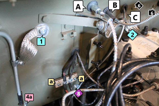
a. Two screws to secure the small junction block to the firewall
8. This is a small clamp that secures the speedometer cable to the firewall.
11, This is a simple clamp, screw and nut that secures the oil line to the firewall to prevent movement. Make sure to install it over the loom to prevent chafing.
14. THis is an additional clmap and small bolt that keeps the large wire harness from moving around on the firewall.
Body Side Step Installation
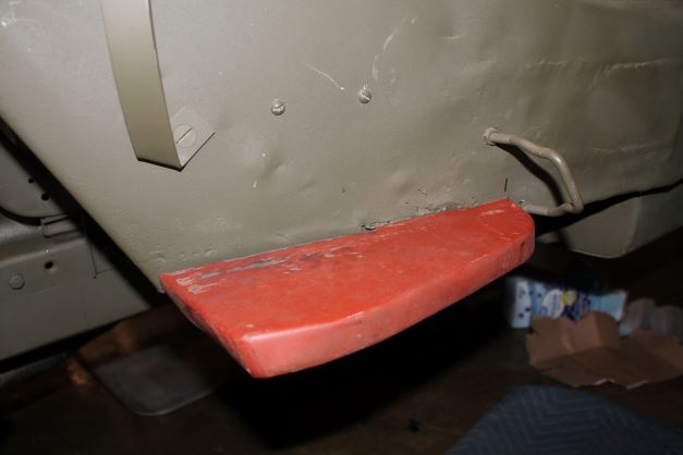
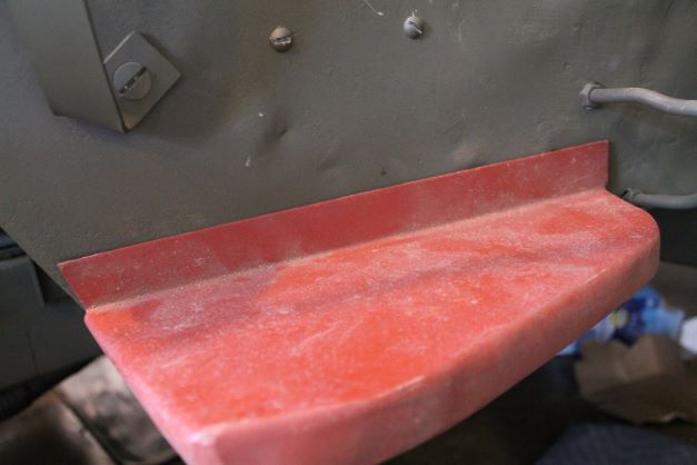
This tub did not have the side steps installed. I have two reproduction steps that will need to be modified for installation before welding to the tub. The lip on the body side is bent up and should be bent down. There will need to be a notch removed for the fitting of the hat channel.
Body/Floor Mounting Plates and Hardware
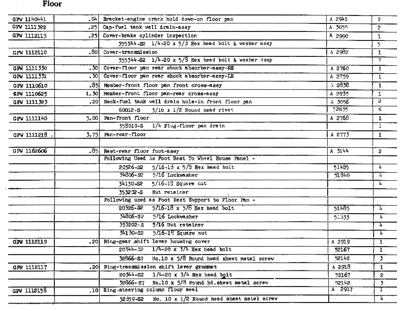
i found this portion of the TM 10-1348 parts Manual a great help for defining hardware to attach all of the selas and covers for the front floor pan.
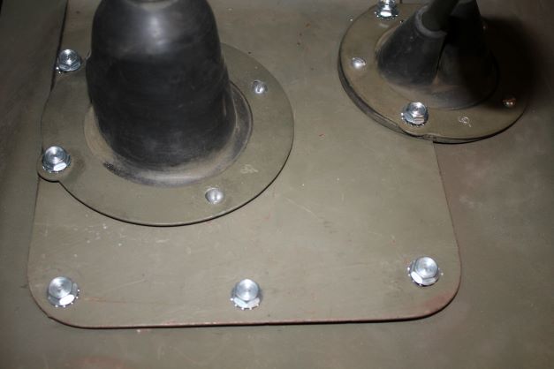
Here is an area of the Transmission/Transfer Case Covers using RFJP special bolts and some vintage cadmium #10 x 3/4 (could not find 5/8) sheet metal screws that I found on-line. The image is before final painting.
Brush Guard Preparation
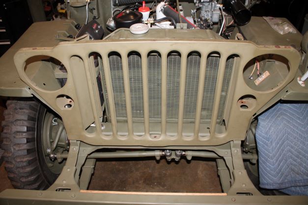
The grill is in very good condition, but it will need some wire wheeling in places and a bit of straightening. From there I will begin the lighting/wiring installation and get it ready to be installed. After cleaning off old paint and small rust spots, I primed teh grill and folled with a bit of dolly work to straighten some of the air baffles and felt attachment points.
I followed with a first coat of OD and a dry fit to check for problems. I also checked all of the capture nuts for the fender to grill attachment bolts and had to replace one nut.
Brush Guard Installation
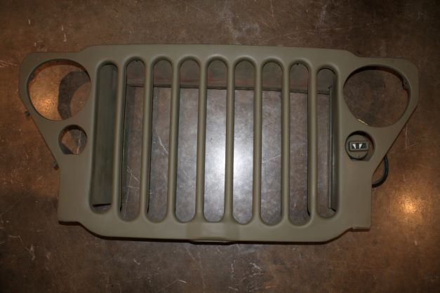
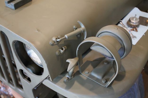
I did some more touch up work on the grill to get it ready to install. The grill welting and rivets, the headlights and marker lights and the felt air dams need to be installed. The lighting will be addressed in the Electrical section.

Brush Guard to Hood Seal GPW 8349
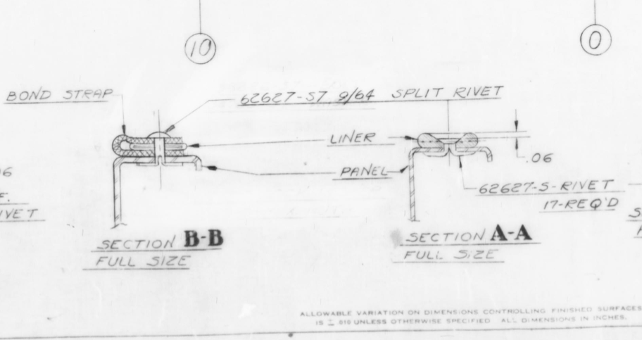
Upon installing the grill welting or Hood to Brush Guard seal material, I consulted the Ford drawings for the methodology. Here are a few drawings that show the details for the simple rivet installatin and the bond strap location and install. Although the drawing below is not quite clear, if you study it closely you can see where the welting starts and stops. I will approximate these drawings when cutting my pieces.
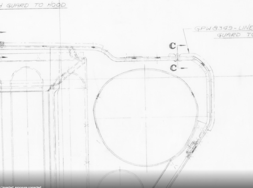
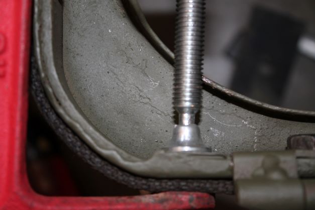
To install the welting I measured and cut the first piece using sharp tin snips to get a clean cut. I lined the welting up and marked the first hole with a sharp punch. I then used a tire repair tool to "file" the hole smooth for the rivet, but not too large. I inserted the rivet and using a screw driver I bent the ears open so that the rivet would not fall out. I then repeated the process for the other rivets. I ended the installation by using a C clamp with a smooth face to press down one ear and then both ears in turn. It made for a nice tight seal.
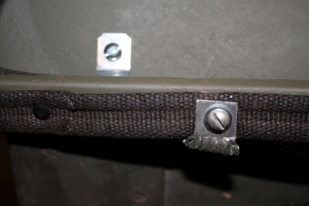
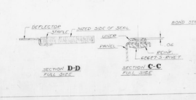
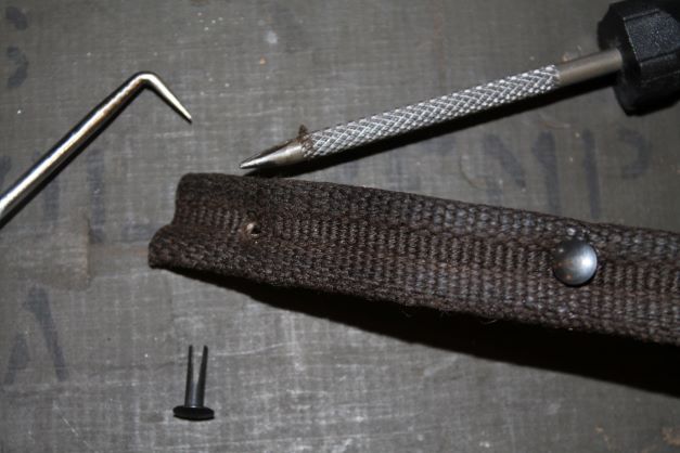
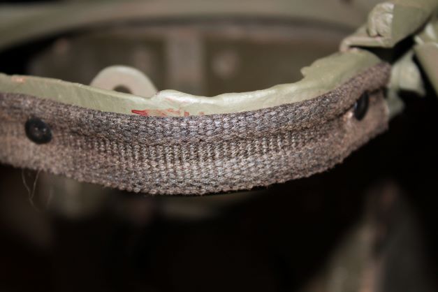
Here you can see the details of the shape of the welting that fits on the two small side rails and is attached with 2 rivets. It looks to be cut at an angle on the engine side.
Radiator Air Deflector
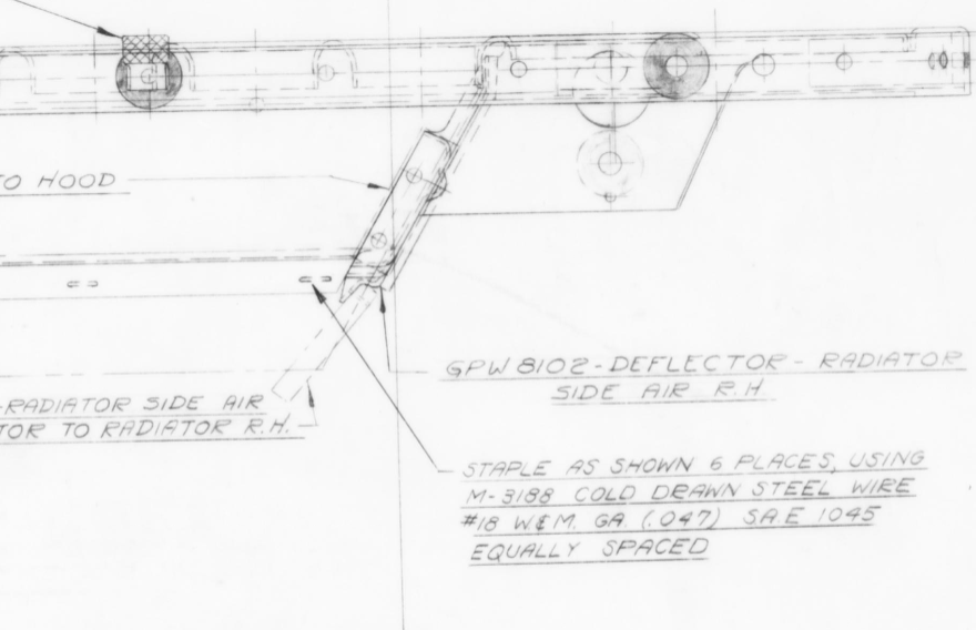
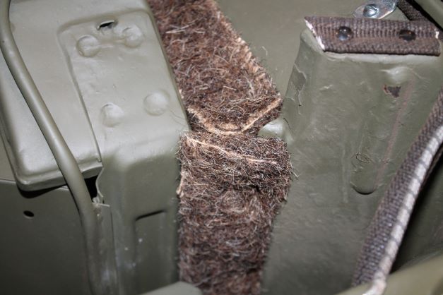
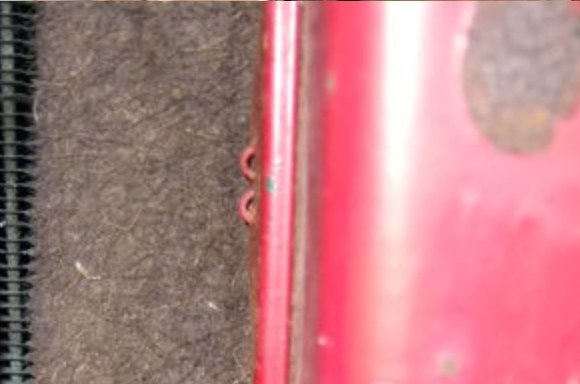
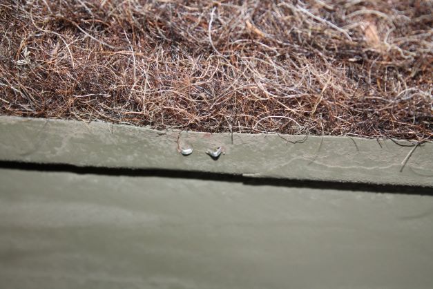
I purchased my air deflector kit from T J Zackman who can be found on the G503. Its authentic to the original and goes on with a bit of tedious work to get the staples in and bent correctly.
I ended up cutting the staples just a bit shorter than provided, and used a vey narrow set of pliers to gently bend the prongs so they look somewhat like the originals as shown in a G503 image copied at right. My bends are not the same, as i suspect there was a particular tool that curled the ends in the shape as shown.
Hood Installation
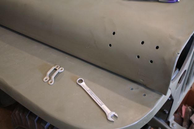
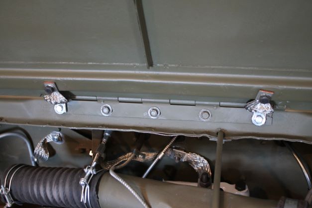
I did not take a lot of images during the hood finishing. The installation went fine although I have larger than usual gaps beneath the driver's side and the fender, whereas the passenger side gap looks acceptable. Moving the hood around a bit after loosening the 5 bolts made a bit of a difference, but they will never be symetrical. Apparently this is not that much of an issue with the fitment.
Rear Panel Reinforcement Kit
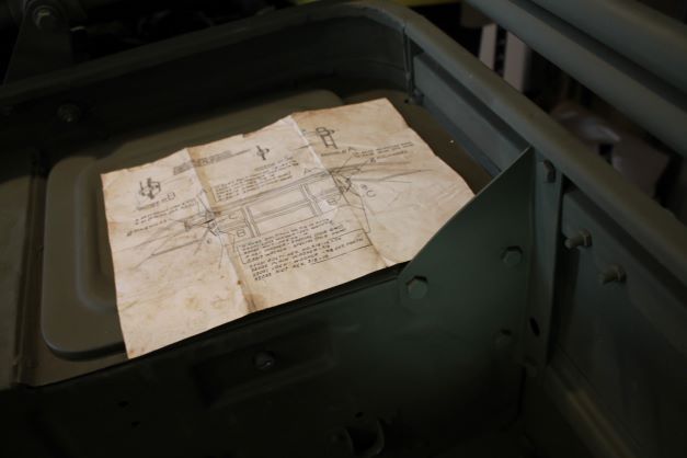
The early production GPWs and Willys were not made with a welded in rear body panel reinforcement piece. It was found that the spare tire and gas can attachments put a lot of stress on the rear panel and cracks developed. The solution was to weld on a reinforcement bracket to stiffen the attachment. For those without the welded panel a kit was sent to the field to make the modification. The kit included all attachment hardware.
I have used a RFJP bracket and vintage 3/8-16 bolts, star lockwashers and washers as directed by the modification kit to attach my brackets. There are two brackets, one for each side/ I have an original instruction sheet that I used for drilling holes and selecting correct hardware.
Invasion Stars and Registration Number
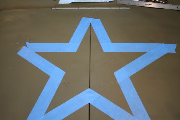
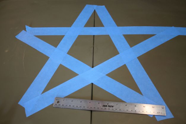
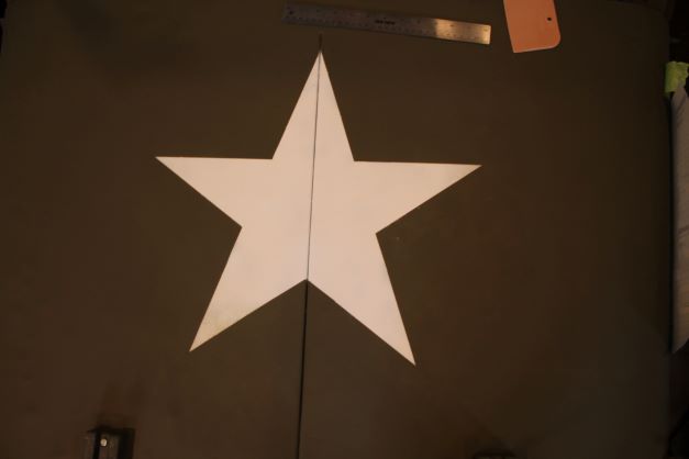
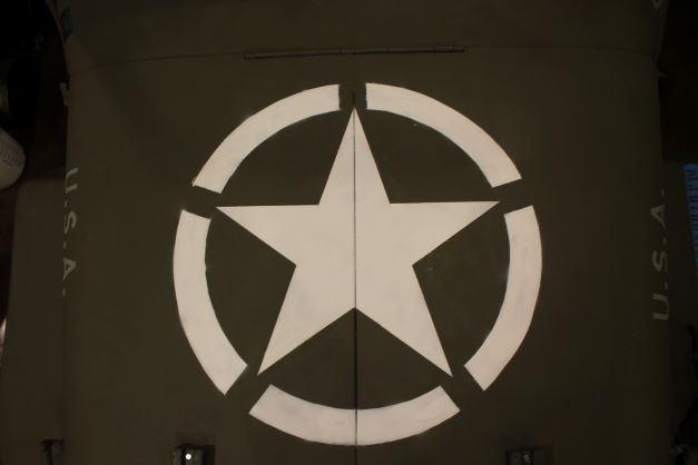
The standard US White Star on the hood should be 20" as it fits in a circle. I used a compass to draw a 20" diameter circle, then segmented it into five, 72 degree segments and connected the dots with tape. The offending portions were cut out leaving a perfect 5 pointed star. I will paint it and then draw the segmented Invasion circle around it. It does not look symetrical because the angle of the camera.
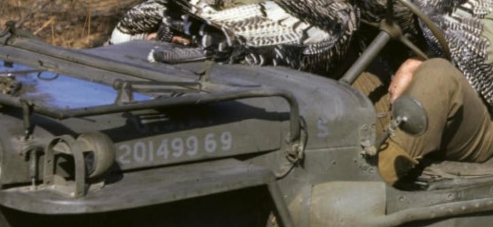
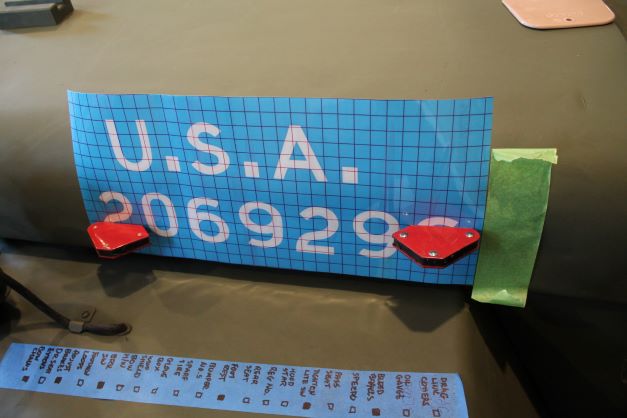
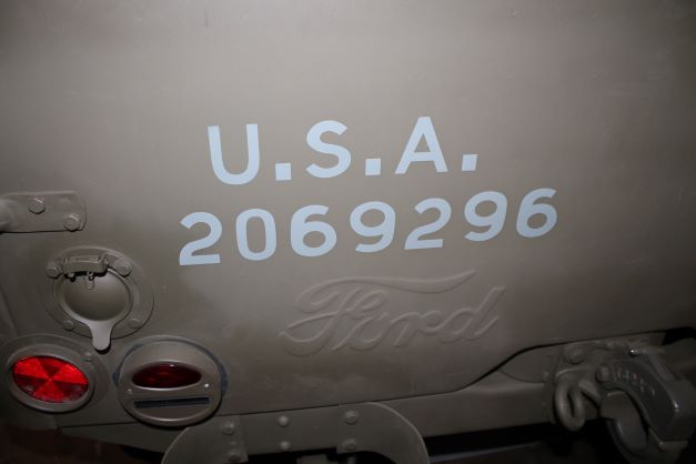
I ordered the Ford style Registration Numbers for the hood and rear panel from T. J. Zackman who is active on the G503. They turned out well. There should be an "S" in blue drab indicating the veichle had the static suppression kit installed. For the Richmond and Louisville plants the S went on the cowl and for other plants such as Dallas it went after the Reg. No

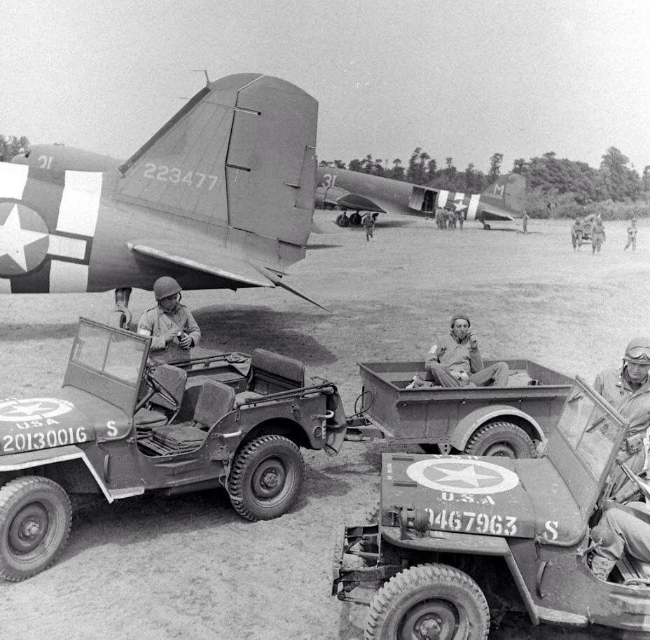
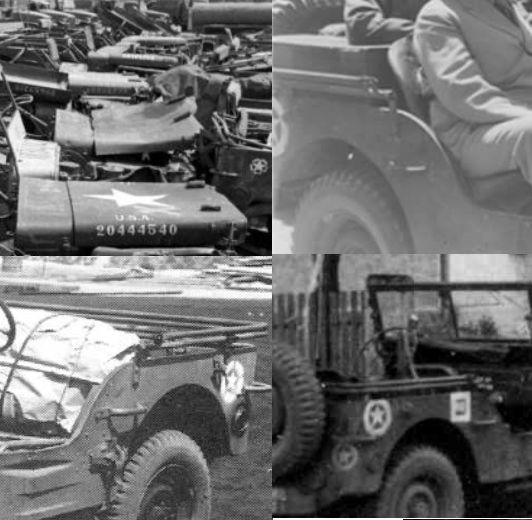
The plain star was painted onto the hood by Ford. Once the Army directed the use of the "Invasion Star", with the circle around it, units used various methods to add the circle around the star. These would be from crude hand painting to cut stencils. You may see a bit of bleed-through, overspray or brushmarks. The circles would either be segmented or not. as seen in the image below. Note also the differences in the number font. For the Normandy invasion it was directed to paint the inner circle around the star with a Vessicant paint that would change color to detect the presence of chemical agents. I cannot confirm if the 17th used this. In any case the pale yellow vessicant would have been hand painted. The 17th Airborne arrived in England in the fall of 1944 and would have used many of these types of methods to add the star. I will make a cardstock stencil and use spray paint to add the white.
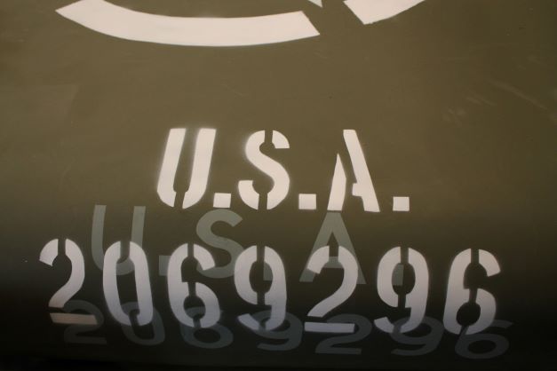
I am not pleased with the font I have for the white registration numbers. It has that modern look. I'll address a change on one of my future projects, and leave this alone for now.
T. J. Zackman sent me this great original color image of the style of Registration Number stencilling done by Ford. As you can see it is not done perfeectly alligned with differing spacing horizontally and vertically. A asked him to make mine slightly imperfect, which he did.

Quarter Panel Stars
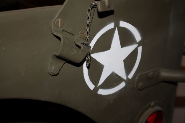
On the side of the GPW, near the rear of the quarter panel there is supposed to be another white identification star. As far as I can determine it was supposed to be 6", although examples exist in 4", 5" and perhaps other variations. Here is a small collage of stars with broken or solid circles in the "Invasion" style. The size seems to vary as well. Note the overspray on the circle in the lower left portion of the image at right.
In most cases, the star did not receive the solid or broken circle around it as on the hood, but there are numerous photos indicating it was done. I have elected to create a card stock stencil with a 5" star and a broken invasion circle. The 6" star with circle just does not fit between the bow hardware and the grab handle. Again, I am assuming it was done by the motor pool with a bit of haste and some underspray or bleed.
Unit Markings and Other Stencils
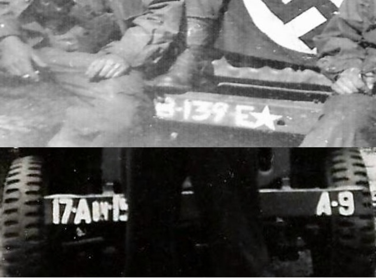
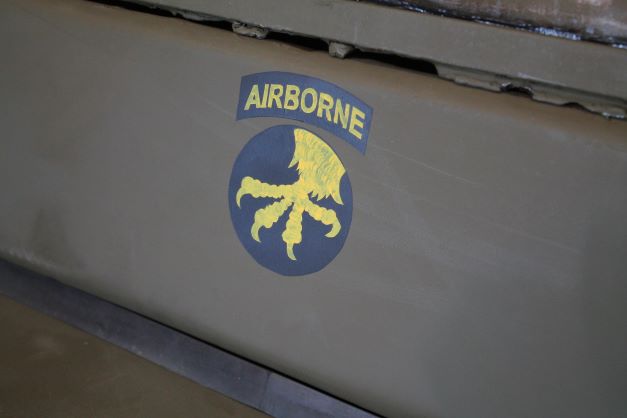
Each vehicle received what is sometimes referred to as the bumper number. It was a stencil that went on the front and rear bumper and desisgnated the unit of assignment and the number of the vehicle in the convoy. So the 13th vehicle in a standard convoy line-up for Baker Company would have a bumper number of B-13. That would appear on the right side of the bumper and the parent unit would appear on the left side. In this case GPW 14518 will be 17A/B 139E B-13, for the 13th vehicle in Baker Company, 139th Airborne Engineer Battalion of the 17th Airborne Division.
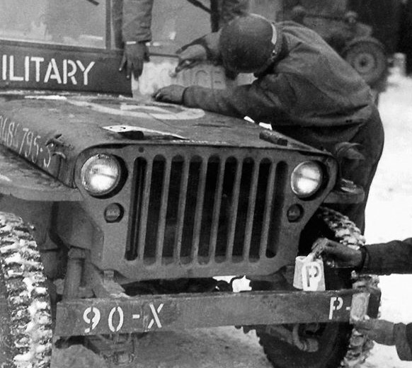
If you consider in the field and at times in the motor pool they did not have the perfectly cut paint masks to make perfect stencils as Ford did, so many different levels of expertise or poor craftmanship are observed in actual photos. I'm sure there are some examples of perfect work done by those who may have done work as sign painters before the war, but this will not be my case. During the war and in the field, the most precise application was done using a stencil brush as shown in this image below. Notice these guys are out in the open, in the field and are using cardstock stencils probably cut by hand after tracing around the brass stencil set. They are using the round stencil brush to apply in a bry brush technique.
I am recreating a 17th AB GPW and from my experience in looking at their work in period images, there was a wide array of methodology and differing stencils and handy work used. I will recreate an application done either in the field or the motor pool, done to the best of thier ability at the time, which would have been hand cut stencils made from tracings on card stock (oil board) and cut out with a razor blade and then held over the part to be stencilled with tape or by hand. In many occasions, a stencil brush was used also. Here are 2 examples of 17th A/B bumper numbers:
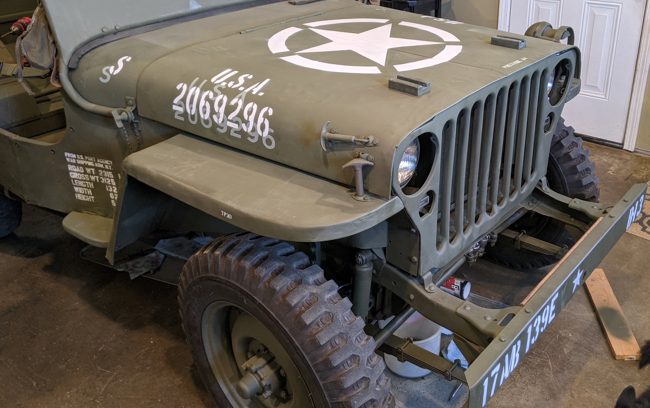
Here is my rendition of the markings done by the motor pool using a stencil traced on card stock, cut out with a razor and then held in place while sprayed. Note the bit of underspray between the letters and overspray where the masking ends.

On occasion you find the odd Jeep with art work and a nickname. The allowance for art was not widespread at all, and images like this are rather rare.
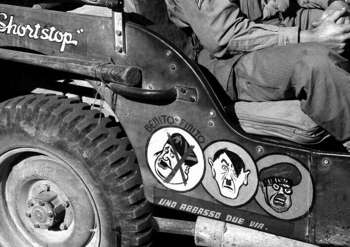
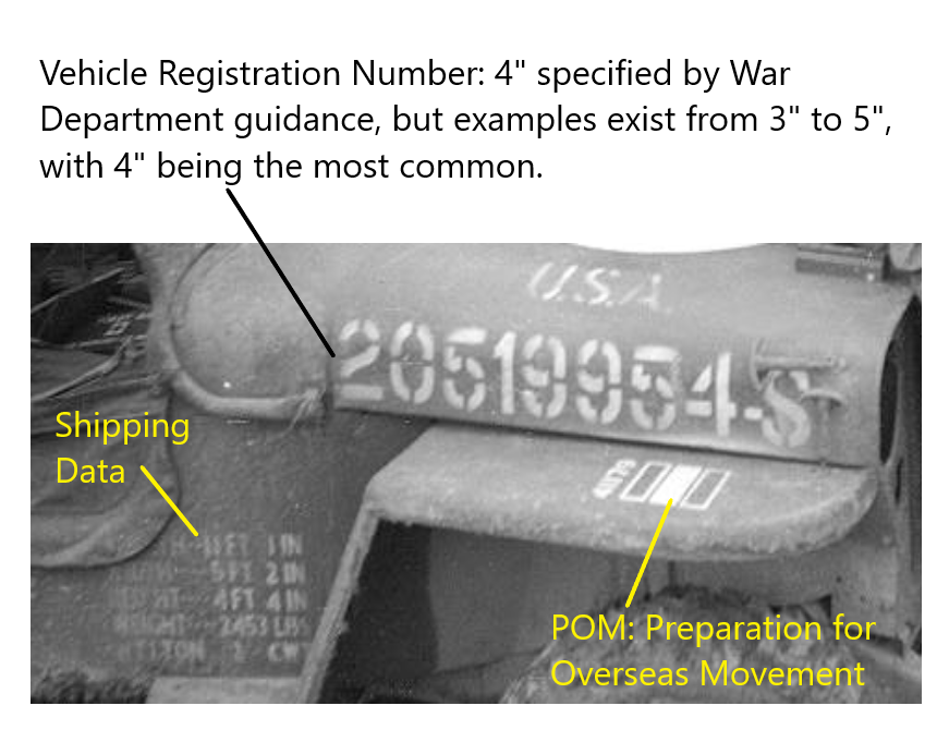
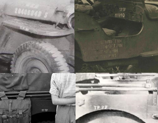
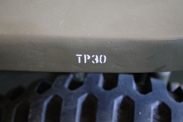
In many cases you will see Post Speed Limit stencilled on the dash, tire pressures for road or cross country on the dash or on the fenders, nick-names of the Jeep, occasionally rank and last name of driver or Commander (rarely seen) and the shipping stencil for vehicles that did not have a netal shipping tag affixed indicating dimentsions and weight. I have seen images of tire pressure at 25, 27, 30 and 35, some indicating CC (cross country) at lower pressure.
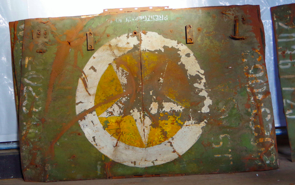
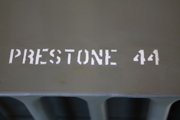
Often seen is a stencil denoting when the radiator was serviced. This would usually appear as PRESTONE44, denoting the fill of anti-freeze in 1944 for example. The image below was taken by Christian Straimer and posted on Jalopnik.com. Several original ww2 Jeep hoods were discovered in a barn in Germany. Here is one color image showing the PRESTONE stencil.
Final Note on Painting
Among the many historians and restorers, there are numerous opinions on how to "properly" paint the details of a WW2 vehicle. The bottom line is it is your vehicle, do with it what you want. I tend to aim for a purpose, that being a faithful depiction of a combat vehicle (except perhaps the A/B insignia). Each of the details that I have added can be tied to period pracitce through the many photographs added above.
The one area that I could improve on is the selection of the stencil fonts used for the Registration Numbers and the Unit ID. On my next effort, I will hand draw them using grid paper and period photos of the font to make it look more accurate. For now I will leave it as you see in the picture to the right.
Rear Panel Holes
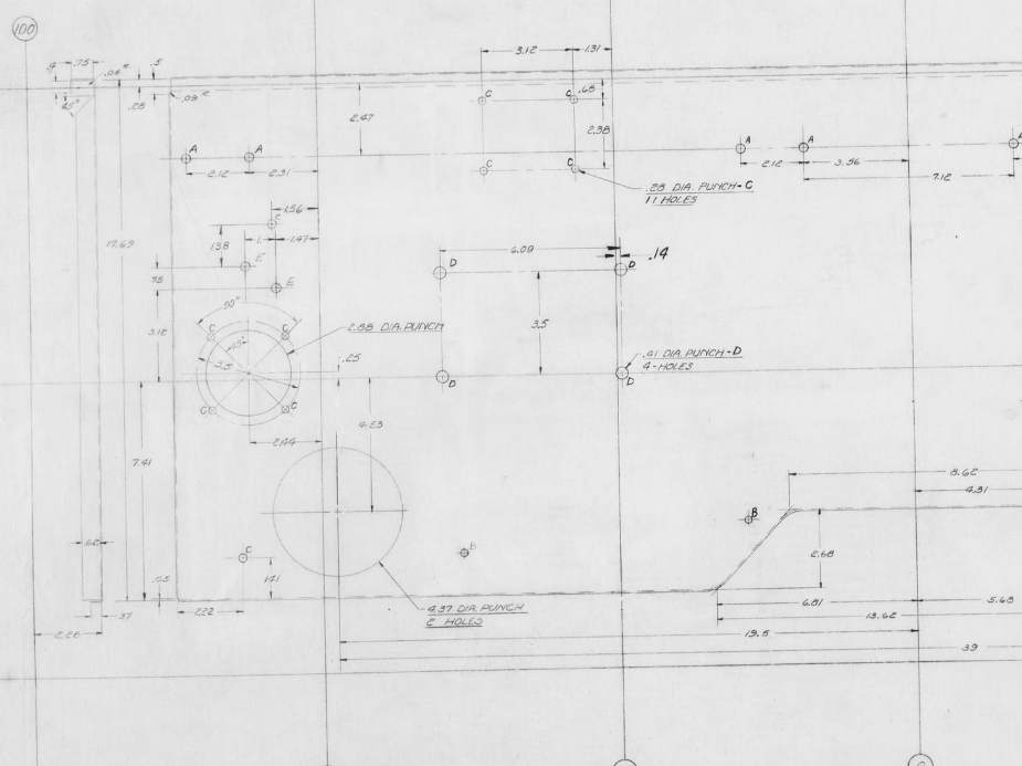
There are numerous holes needed to be drilled in the rear reproduction panel for the footman loops and the early 3-lug tire carrier. I have consulted the GPW drawings to get the locations down. Here is the left and right side of the panel. It seems most measurements are taken from the center line of the panel.
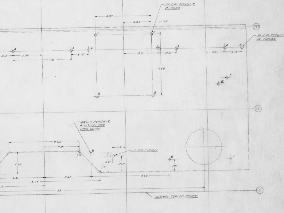
There are 14 Footman's Loops on the GPW if you mount the Fuel Can strap holed. If not using that, then an extra loop is needed. I am not sure n the placement of that just yet
- 2 on the top bow tubes
- 3 for the pioneer tools
- 4 under the passenger seat to hold the top canvas
- 5 on the back panel (6 if not using the can strap holder)
Passenger Seat Repair
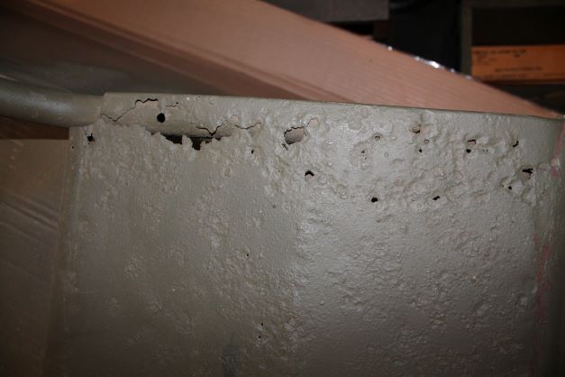
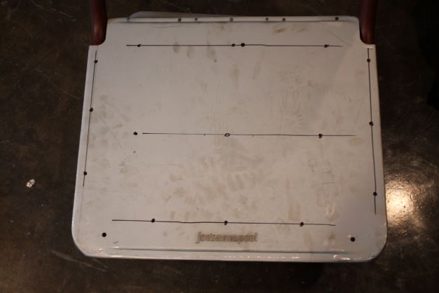
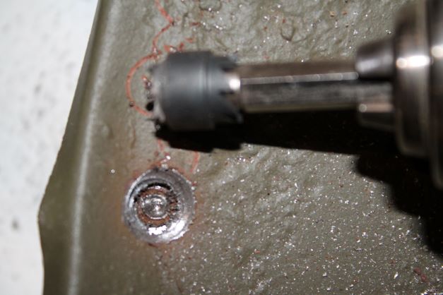
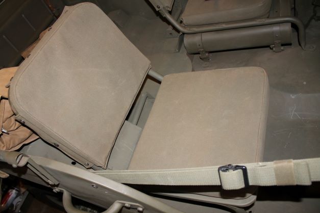
The seat pan of the Ford marked passenger seat is in rather poor shape, so I will replace it with JMP pan. It might be salvageable at a later date, so I will keep it and see. For now I will use a hole drill to remove the spot welds and weld the new pan in place. I might have to do a bit of repair to the frame.
WIndshield
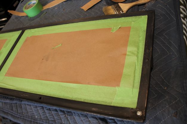
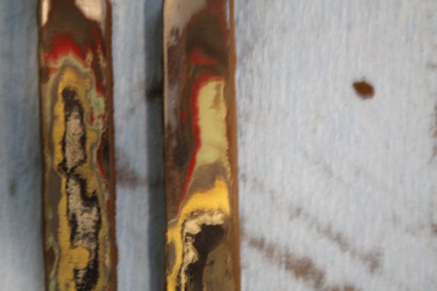
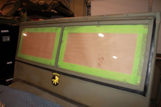
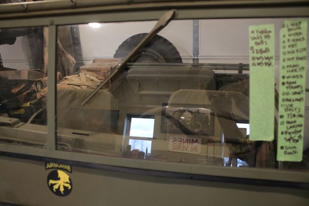
The windshield that came with theis GPW had several issues that need attention. I will rebuild the frame and glass later and for now installed my best winshiled int he frame. I cleaned up the adjustment arms and found 9 different coats of paint on them giving the history of the windshield. I added a new rubber outer gasket and replaced the hardware with correct #10 screws and inner lock washers etc. I repainted the frame and installed a RFJP adjustment arm hardware kit.
I havew one NOS winshield wiper and have another repro to install giving this '42 a corect configuration of 2 individual non-connected wipers.
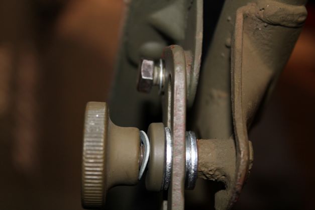
I've included an image of the swing arm attachment bracket and hardware here before painting. The nut used to hold the pivot point should be a flathead slotted #10x28 screw (not sure of the length). I have a hex head nut in its place for now.
Axe and Shovel
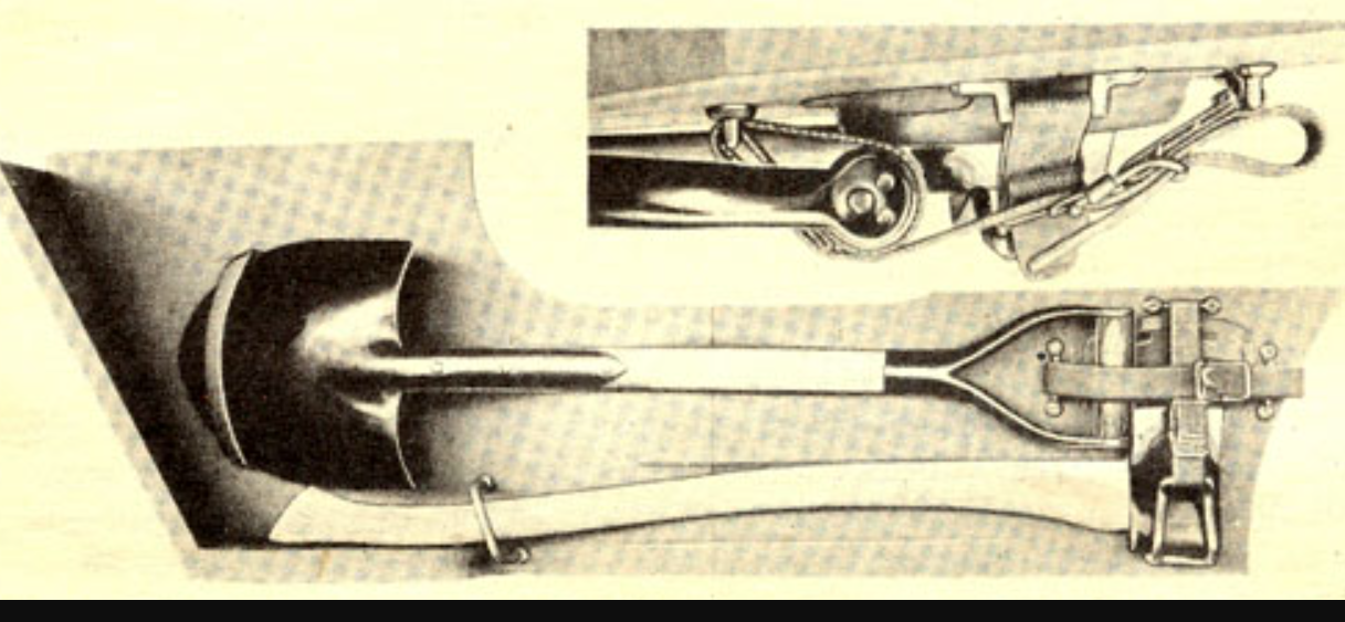
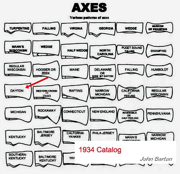
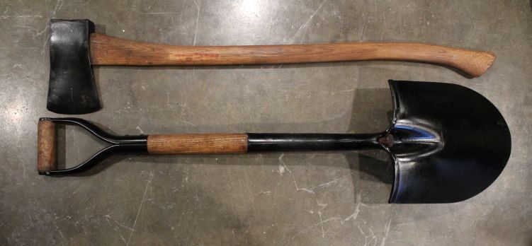
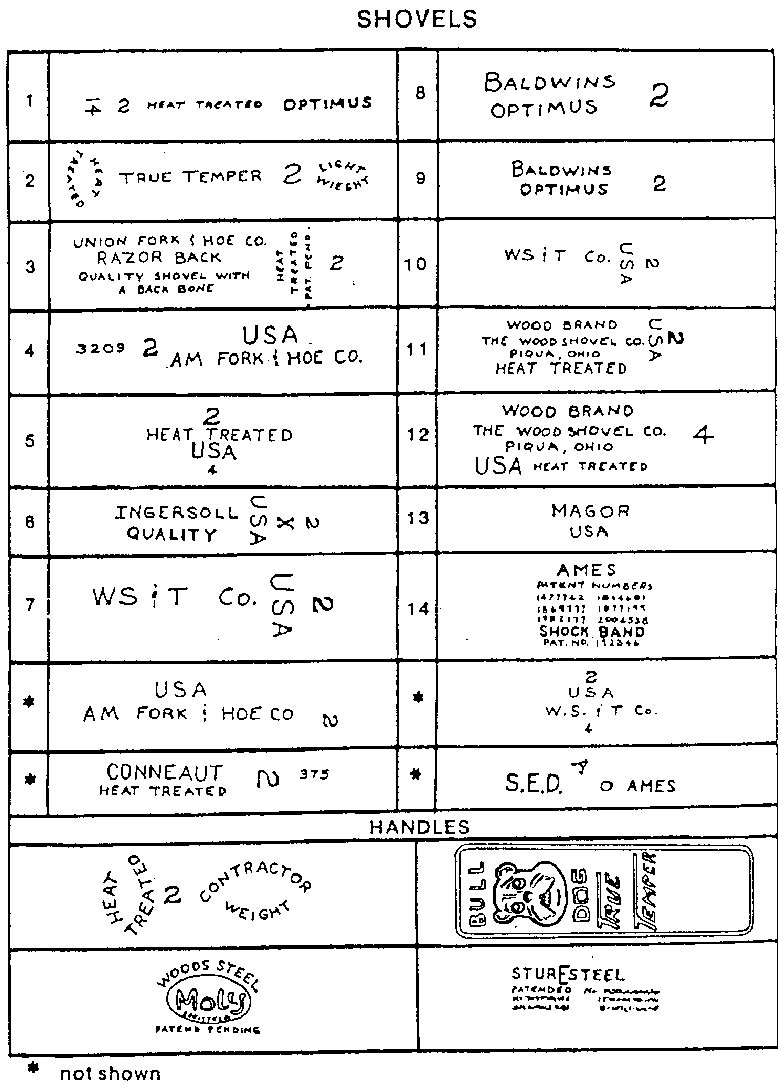
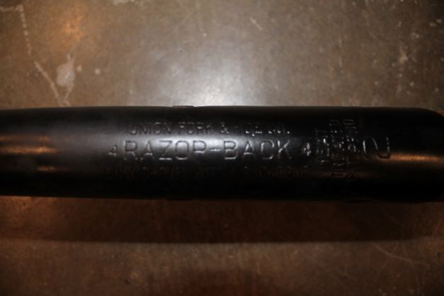
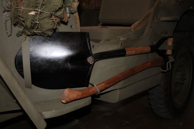
John Barton was a pioneer in the documentation of tools for the WW2 Jeep. He has some great material on the G503 about shovels and axes. I have added the images here with credit to him, It seems that the variation in paint/finish on the axe and shovel is greater than one would expect. One could portray all OD, OD and natural wood, black metal, natural wood and totally unfinished. Many use boiled linseed oil for the wood. It gives it a natural and slightly darker appearance.
Original WW2 Camouflage Net
Punch Out List
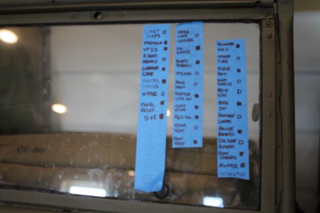
Rather than detail a section on each of the remaining body items i have left, i am simply posting a Punch Out List of the remaining things left to bring the GPW to completion. I'll take care of these items over the coming weeks and close this restoration thread out except perhaps to make corrections and post a few final pics.
