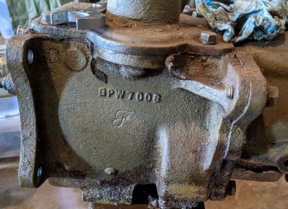
BEFORE
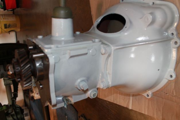
AFTER
Tear Down Begins
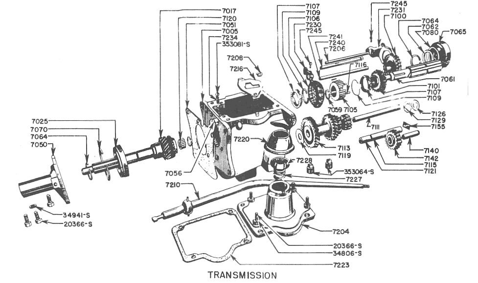
For the Follow-on discussions of the transmission rebuild, I'll generally refer to the parts diagram above taken from the parts Manual.
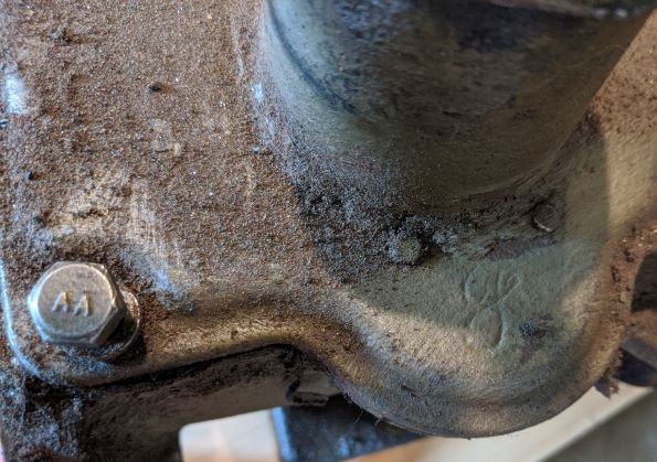
I removed the transmission and gave it a cursory inspection. The top cover bolts are marked AA. I plan on replacing them with F marked bolts. On the surface, everything appears to be normal, and I have an early Right-hand side fill transmission case.
I removed the top cover to get a peek inside. One gear has some teeth damage. Will get better pics later, and also have my TM open to ID parts properly for the post.
Of note I did not find the small Spring Washer 7206 listed in the Parts TM. I suspect it's easy to obtain, and hopefylly not ground up in the bottom of the case.
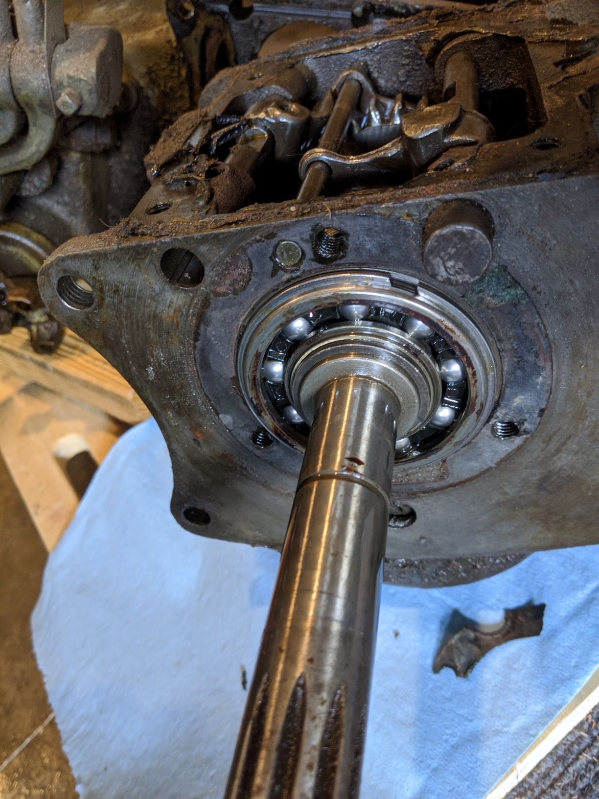
Worn Parts
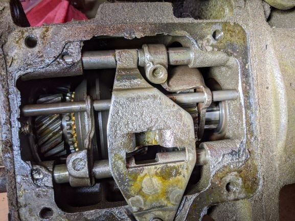
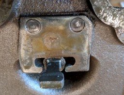
When you remove the top transmission cover 7204, I noticed the Shifter Guide Plate arms are worn. As you can see, there is damage to the fingers on this part more than 3/8" between them and this part is out of spec.....get a new one and rivets and install it TIGHT to the tower!
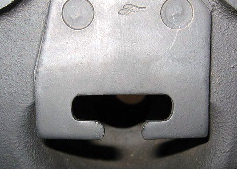
This is what a nearly new part should look like. (Image provided by Chuck Lutz) The damaged gates will make shifting somewhat "sloopy" Installation kits are available through the typical parts suppliers and come with two rivets. I'll detail installation later.
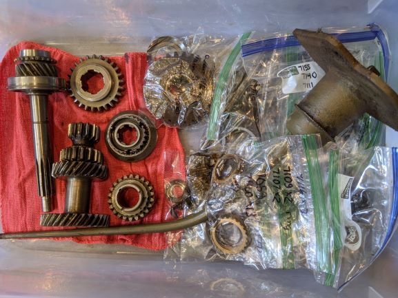
Bagged and Tagged
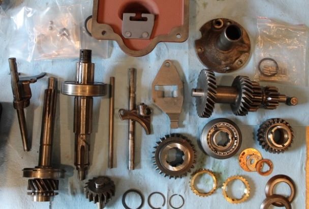
Finished tearing down the transmission today. Everything is bagged and tagged. Will clean and inspect components for servicability, then make a list $$$. Here is an image before the tear-down began with only the front bearing cap removed.
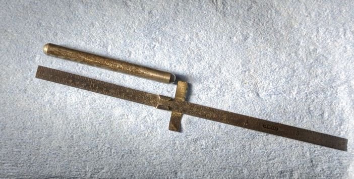
When i split the transmission and transfer cases, this little puppy rolled out. It is a pin, 2.5" long x 0.25" diameter. (sitting astride a steel ruler) I could not find it in TM 10-1348. It is the Interlock Plunger.
Damaged Thrust Washers
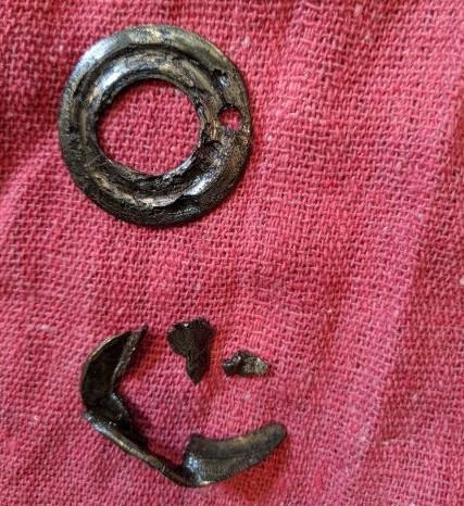
Found in the bottom of the case, Part No. 7126 Rear Thrust Washer and 7129 Thrust Washer. And this is why I always tear down stuff before assuming its been properly restored. Think of the damage this could have done. Thankfully only a few miles were put on the GPW as it sat in a Ford Showroom for 18 years.
Also, despite taking great care to not lose the springs and poppet balls, I found they were never installed. The more I dig, the more problems I'm finding. Glad I'm doing this restoration of a restoration
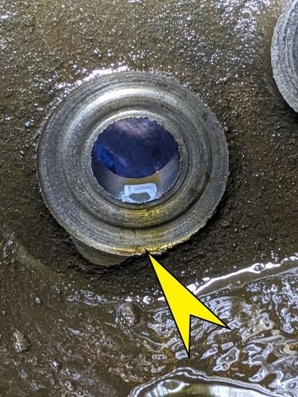
You can clearly see in the two images that the Thrust Washers are heavily damaged and grooved. This wear pattern took a toll on the thrust washer faces inside the transfer case.
There must have been pices of one thrust washer or gear parts sliding around inside the case, between the washer and the facing. It caused heavy wear and completely wore off the pin that holds the washer in place.
Both cluster gear thrust washer faces on the case look pretty bad. Probably due to excessive slop to begin with and as metal particles get between the washers and the case faces, the circular wear marks your case exhibits are the result.
The space between T/W case surfaces are supposed to be between 5.657" - 5.658". A NOS cluster gear will be in the 5.485" - 5.497" range.
Using a micrometer the distance between the face of the inside front and inside rear is 5.782" at best. That is 0.126" greater than the specification. That sounds bad.
The remaining space is taken up by the front T/W, the rear BRONZE T/W and the STEEL T/W with the hole for the pin.
The TM 9-803 calls for 0.003" - 0.014" SLOP here but the G503 guys have long suggested you go with 0.003" - 0.006" at the most.
So, can this case be used? No, I will have to find a new one.
Gear Inspection
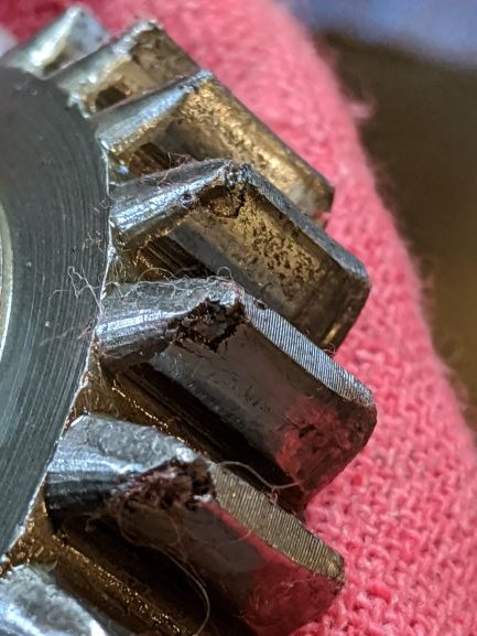
Continuing with the inspection of the parts. There are some chipped teeth in the Low and Reverse Sliding Gear Part No. GPW 7100. WIll source another if needed.
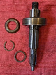
The Main Shaft and bearing look solid. I had a time getting that stiff snap ring off even with special pliers. I have the type for the perforated snap rings and they were not working as well.
Main Shaft GPW 7061
Bearing GPW 7065
Main Shaft Bearing Spacer GPW 7062
Snap Ring Main Shaft to Drive Gear Bearing GPW 7064
Main Shaft Oil Baffle GPW 7080
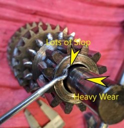
Here is the Counter Shaft Gear GPW 7113 mounted on the Counter Shaft GPW 7111.
I miked the shaft and there are some wear spots that you can see on the shaft. The diameter around the wear spots is 0.012" less than the rest of the shaft. Notice the difference between the ID of the gear and the OD of the shaft. Lots of room in there, whereas at the front of the gear there is minimal side to side movement. There is a bronze bushing in the front of the gear, but none in the rear. In any case I will source a new shaft (so to speak)
Continuing Inspection
I began the TM inspection process tonight. Looking at gears and shafts (so to speak) from p.18 and beyond.
b. Inspection and Repair.
(1) Transmission Case Assembly: I find the case to be serviceable, lightly worn with no damage or cracks, cleaned, blasted and primed.
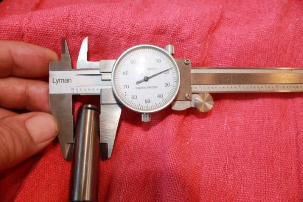
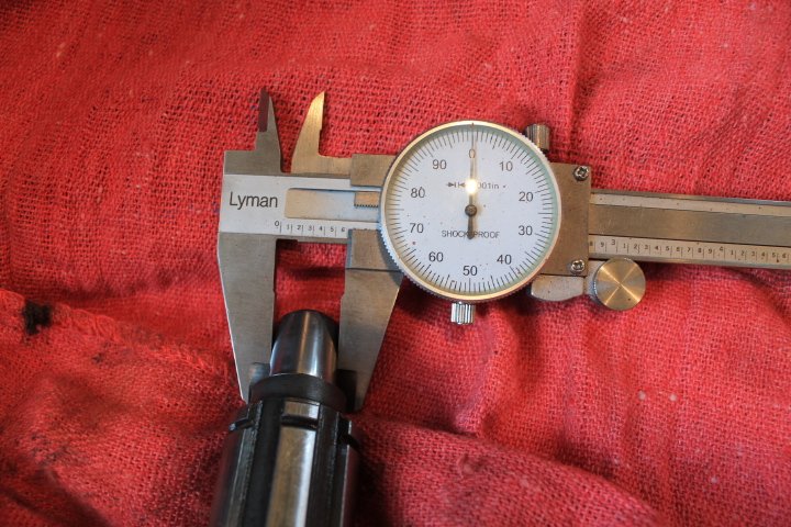
(2) Main Drive Gear Assembly: Minor patina, Roller bearing recess at 0.970" The pilot end of the shaft is 0."639" Does not jive with TM so i expect there is an error there.
(3) Mainshaft: Not pitted or excessively worn. Second gear measurement 1.129" and pilot end 0.600"
(4) First and Reverse Gear: Problem...back lash about 0.013" which is far greater than the 0.005" tolerance. I will probably replace that gear and recheck so as not to have to replace the shaft unless it is causing the backlash. Here is a small video of the backlash.
(5) Second Gear: I have a new US manufactured gear coming in.
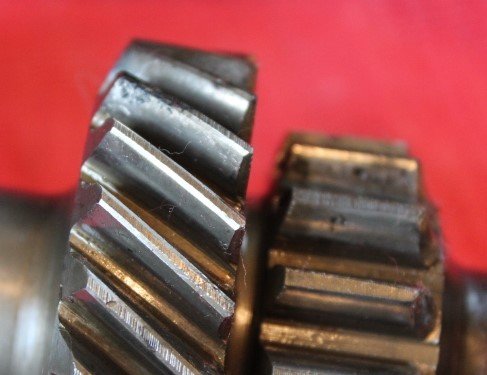
(6) Countershaft Gear: I have new bushings and spacer to replace. There is some light to moderate pitting in some of the gears.
(7) Idler GEar bushing: Measures 0.621" with some minor patina and small pits
(8) Idle GEar shaft: New US made 0.619 Countershaft measures 0.622 new US made.
(9) Synchronizer I won't be able to check the full fit until my gears come in. The springs and dogs are new. The blocking rings are newish and reproduction. WIll finish evaluation later when I can see how everything meshes together. There is no branding or marks on the blocking rings. I will replace the entire grou with new US made parts.
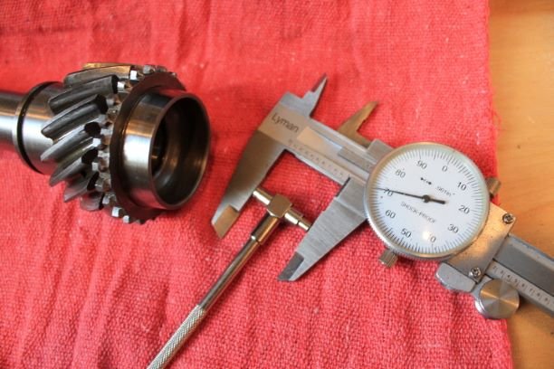
One final inventory before beginning assembly. I should have done this earlier as I only gave the shifter forks and rails a preliminary look over. I missed the deep-ish scoring on both sides of the forks where they "ride" on the grooves in the gears. I read somewhere that comes partly from holding ones palm on the shifter and providing a side force on it while driving. That apparently caused the forks to ride against the grooves and wear out the forks prematurely. Somehow I left out the shaft lock plate GPW 7155. I still need to seat the shifter plate rivets in the cover. Will be getting an impact hammer and some rivet anvils for that job. Should come in handy.
In any case I will need to order a few more parts. That's a good thing as my wife loves checking the mail and proclaiming "parts is parts" when the goodies arrive.

Following the TM Assembly Procedures
Step A: Install Idle Gear
From : TM 9-18038
Here are the Transmission Assembly Instructions I will follow, which I will supplement from comments from John Barton's Pages found on the website G503. His comments apear after JB, and mine added as OZ
ASSEMBLY.
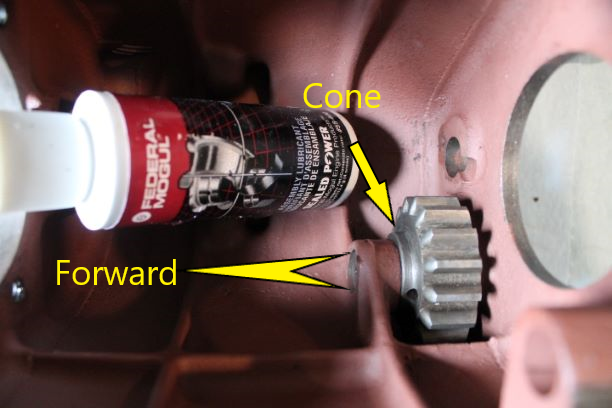
a. Install Idle Gear. Hold the idle gear (fig. 15) in place in
the case with the cone end of the hub toward the front, and push the
idle gear shaft into the case.
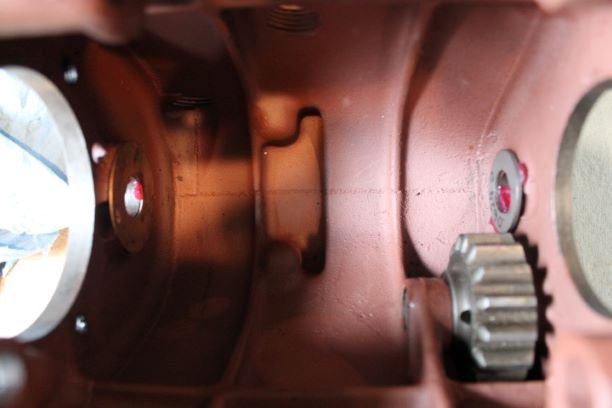
JB: "Then idler gear…cone end toward front, Insert shaft from rear…pay attention to notch on
shaft…the notch must line up to accept locking plate.. And this small shaft is harder to turn when all the way in.. The locking plate will do a final line up.. but easier to set it close now."
OZ: John installs his idle gear after the cluster gear. I have read both ways. I used a bit of Mogul Assembly Lube on the shaft to provide initial lube for the gear. It spins easily on the shaft, but not with lateral play. This is a new shaft and NOS gear. The cone is installed forward.
Step B: Install Countershaft Gear
b. Install Countershaft Gear (fig. 14). Dip the countershaft
bearings into SAE 90 oil. Slide the spacer into the countershaft gear
and install a bushing in each end of the countershaft gear. Coat the
front thrust washer, rear thrust washer, and steel washer with a light
film of grease to hold them in place while installing the gear. Lay
the countershaft gear in the case with the large gear toward the front.
JB: "The earlier section had pics of the index pin and front notches and how to set etc..tilt the gear so back end goes out rear bearing hole.. Level it off, line it up, and lower… it will probably take a few times…the fit between washers is slim, I usually knock them off a few times before I get it right. Let it drop to the bottom. Sometimes the fit is very tight…I have had to play with different combinations of thrust washers etc.. I did measure the thicknesses once....there were several variations. I have lapped them down.. and cleaned up the case surface if necessary. When I do get it to set right.. I test fit everything by using this Sears rolling pin pry bar as a substitute mainshaft.. hold gear with one hand…raise it slightly and slide bar in.. I roll the gear, get grease spread out to hold washers.. From now on…try not to turn case to much…you want the Thrust washers to stay in place.. The manual says put the idler in first…I find it easier to put the cluster assemble in first."
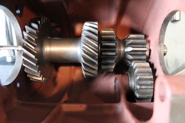
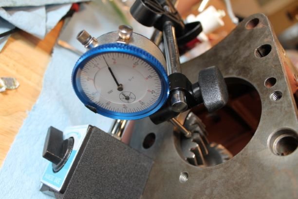
Oz-way: I selected the correct combination of washers that would give me a bit of movement between the case surface and the countershaft. If the washer combination is too fat, the countershaft will bind and there will be a lot of friction between the elements causing prematue wear. Here are the steps I used.
1.I used some heavy grease to tack the front and rear thrust washers to the case ensuring the tang was in the grove in front and the pin inside the index hole on the rear. I also lubed the bearings
2. I lowered the cluster gear into the case letting it set on the bottom
3. I slid the counter shaft into the hole only enough to secure the rear steel washer.
4. There is just enough space to slide the bronze washer in place from above between the back of the cluster and the steel washer. I pushed the shaft farther in to "catch" the steel washer, and then nearly all the way in to catch the front washer ensuring the tang was still in the grove.
5. I measured the fore/aft movement at 0.003" I suspect that will increase over time
Step C: Install Mainshaft Assembly
c. Install Mainshaft Assembly (fig. 13). Insert the mainshaft in the case through the opening in the rear of the case. Slide the first and reverse gear onto the shaft, with the shifter fork channel toward the rear. Slide the second gear onto the mainshaft with the tapered end of the gear toward the front. Install a blocking ring onto the second gear. Slide the synchronizer onto the mainshaft with the long end of the hub toward the front and install the snap ring,.
JB: "The next part to go in is output shaft…book says Insert from rear of case and slide gears on..It is easier to put gears on and them slide whole assembly in. One of the gears that goes on output shaft is synchro.. the directions in different places are not quite clear on how to do this..You need the springs in.. Locking plates in place, outer hub on.. Some instructions use a clock system, or put in one, turn it over And do same thing, etc.. The easiest explanation of springs is this picture above to the left. Hold the plates with your fingers and slide outer hub over..a little oil helps. Outer hub should slide back and forth.. you’ll see action of plates and springs, the next picture shows various types of locking plates I’ve seen short, curved, long and flat…I have come across many.. I think it is just important to have three matching ones.. You should always buy a new synchro and blocking rings.. the first/reverse gear goes on output shaft, fork channel to rear then second gear. taper toward front.. it only goes on a short distance . Then blocking ring..the small brass gear.. Then synchro…. Long end of hub toward front line up notches in blocking ring with plates on synchro.. put snap ring in front of synchro.. slide gears toward front.. tilt and put back end of assembly out rear hole in case.. just let it sit there..Now assemble the input shaft bearing with snap ring goes on…shielded side toward the case, the snap ring holds it on…"
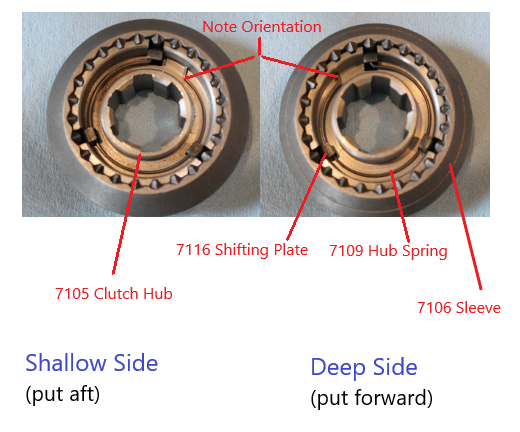
OZ: Here is an image of the clutch hub and components. Note the orientation of the springs and the fact that there is a deep side and a shallow side. John calls the deep side the long side. Place the long/deep side forward.
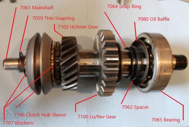
The next image shows the location and orientation of all of the parts on the Main Shaft. Note the front snap ring is loosely hanging for the photo, and the spacers and baffle are just slid on to show the orientation and alignment. Also note that the closed end of the rear bearing should be in toward the transmission case, open end on the outside. Which is not what I am showing!!! This bearing will be replaced with a sealed bearing to prevent oil flow between the transmission and the transfer case. That has been a known deficiency of the early design with open bearings.
Step D: Install Main Drive Gear Assembly
d. Install Main Drive Gear Assembly (fig. 13). Place the other blocking ring in the synchronizer and install the main drive gear assembly in the case.
JB: "Now assemble the input shaft bearing with snap ring goes on…shielded side toward the case, the snap ring holds it on…Now is usually when I call my daughter because my fat fingers won’t fit in to install roller bearings in back end of input grease them up.. she doesn’t like the icky grease!!! the last one has to slide in from top.. sharp needle nose… the snap ring that holds them in doesn’t really touch them.. never taken that snap ring out.. I guess if you buy a new input shaft it will come without it.. It's a little tricky to install.. pliers.. screwdrivers, etc..again- you need to be careful now.. if you drop or set it down too hard.. the bearings will fall out.. now comes another tricky part… put other blocking ring in place.. use grease to hold in in synchro or put it on back of input shaft and line up notches again..You now need to slide the rear bearing on to line up output shaft.. after the spacer and oil baffle.. snap ring is already on.. If you get fit correct first time.. it will look like this, if not…one of the rollers fell out…they won’t mesh.. you’ll be able to tell.. because you’ll feel it grinding etc.. gentle tapping on the bearing may be necessary to finish.. I try to insert the output shaft tip.. into the roller bearings, and them tap the front bearing into case...keeps the rollers from falling.. hold on to both shafts from now on while moving… if either moves out.. the roller bearing or blocking ring can fall out of place.. with both shafts in place.. some people wire them ..to hold them.."
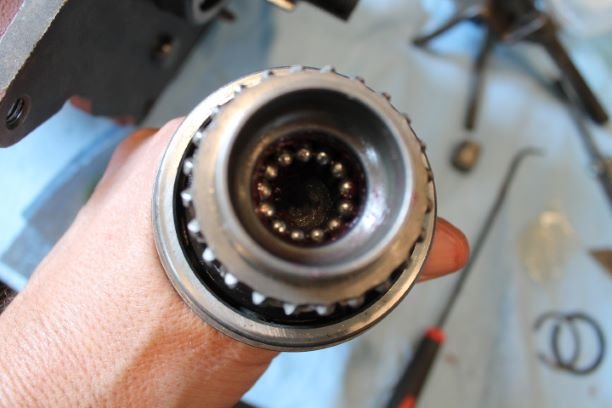
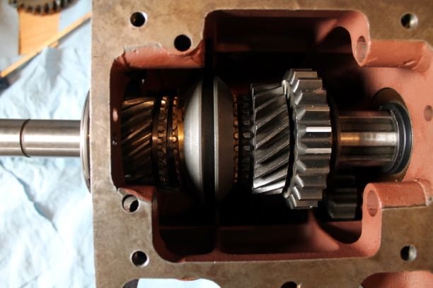
Oz: As you can see from the image above, I wanted to check a few things before installing the input shaft. I did not want to get into issues before at least measuring the fitment. Again, Installing those snap rings is a bugger.
I put some bearing grease in the recess where the bearings go behind the thin snap ring. That went in very easily by hand. I installed all 13 bearings one at a time. The 13th one has to slide in between two bearings in the open gap. You can't press it in between the two, you have to insert it lengthwise into the groove. I found the use of a shifter rail keeps everything together.
Step E: Install Countershaft
e. Install Countershaft. Raise the countershaft gear into position.
Making sure the three washers are in line, push the countershaft into
the case and tap the lock plate between the countershaft and idle
gear shaft.
JB: "Just be careful.. you’re ready to raise the countershaft gear.. you can’t get the input shaft in with the countershaft in place.. so don’t try to do that before now.. Here’s what I do…there are other methods. I turn the case on its side with the idler gear down..it helps locate the Countershaft gear..I use the rolling head pry bar again..from the front..It is sharply tapered so it can usuall get thru the thrustwashers..which settled with gear..I slowly and gently try to get it all the way through..Turn the case completely upside down..Turn the input shaft…that helps center and line up the countershaft gear and washers..
Now the trick is to replace the prybar with the mainshaft..Insert from rear…line up notches for lockplate again..Some people have a special tool machined..probably easier to insert mainshaft. As you slide the tool out….either way..? you can do it without any tool…
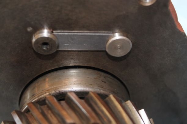
When case is upside down..if you turn the gears..the countershaft will center itself..Put lockplate in place..leave mainshaft out just a hair..after front end is lined up..tap both shafts with hammer. if notches are not lined up exactly..the lockplate may turn them into position..or you may need to turn the shafts…look at the neat “F” on extra lockplate..Rotate the gearbox upright, be careful that the gears don't slip out . Now if you have lined everything up…it should look like this."
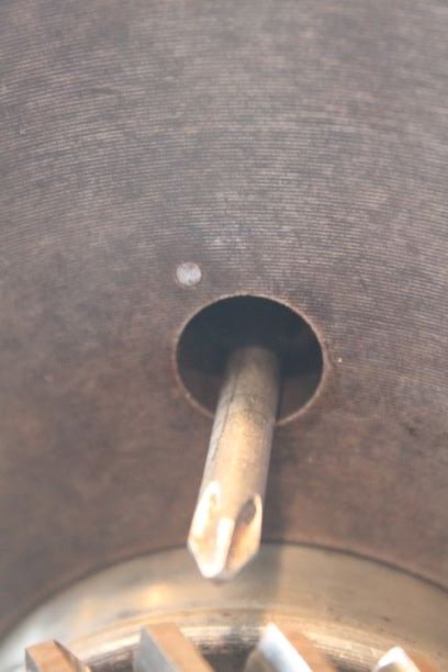
Oz: I simply rotated the case upside down being careful not to dislodge anything and kept the Phillips screwdriver in place. A few gentle rolls of the Main Shaft Gear on the back allowed the cluster gear to "seat" itself in proper alignment. I used the shaft of the driver to lift and jostle the two rear washers in place.
CAREFUL NOW: Keep pressure on the Phillips screwdriver from the front WHILE gently sliding the counter gear shaft against the head of the driver. You will feel the washer slipping into place and the shaft slides freely into the cluster and out the front. Just keep the head of the screwdriver "mated with light pressure" to the shaft and nothing will slip out. Don't forget to align the spline for the lock in the rear and make sure the idle gear shaft is out and aligned also.
Some Notes on Shimming
At some point I will add some images and comments on how I shimmed the gears and synchronizers to ensure problem free shifting. These notes come from the G503 member posts.
1. The input shaft with direct/3rd gear is fixed & not adjustable.
2. The mainshaft has 2nd gear, baulking ring/s, drive & second hub & selector sleeve circlipped in a fixed position & is non adjustable.
3. It also has 1/R sliding gear.
4. Then there is a circlip, spacer/s & THE ball bearing.
5. This ball bearing's position on the mainshaft is adjustable but once mainshaft position is adjusted the bearing is locked in place
6. Decreasing the shim spacer thickness moves the mainshaft rearwards & increasing moves the mainshaft forward inside the case
BUT doing either of these things moves all the parts mentioned in 2 because their mainshaft position is fixed.
7. Those things in 6 are used as an adjustment for baulking ring positioning/optimum operation plus we don't want the mainshaft bottoming in the input shaft needle roller recess.
8. To check for correct adjustment we assemble all the needed bits to the main shaft through to the circlip, spacer & bearing.
9. We fix all these to the mainshaft by torquing the main drive gear & washer to them with the castellated nut.
10. Now we clamp the mainshaft & bearing tightly in the transmission case recess.
NO SHAFT or BEARING MOVEMENT either way except oil clearance....GET IT!
11. Check to ensure the things mentioned in 7.
12. If too tight, remove bearing & appropriate amount of spacer between bearing & circlip. Too loose then add spacer between bearing & circlip.
13. Once correctly adjusted remove the bearing clamp & bolt up the transfer case, refit the gear, washer & castellated nut.
Remember the bearing was clamped tight in the transmission case when your adjustments were completed properly....it needs to be 'exactly' the same now.
14. If there is ANY bearing movement of concern it will only be rearward if the transfer case cavity is not acting exactly the same as the set-up clamp was.
15. Depending on how much this mainshaft bearing movement forward & rear is means your mainshaft position inside the transmission case becomes variable between spot on when up against the transmission housing & looser than you set things at when right back against the transfer case housing. That is not desirable.
16. With a dial gauge measure this movement & ONLY shim the transfer case bearing recess.
Shimming to Set the Slop in the Blocking Rings
At some point I will add some images and comments on how I shimmed the gears and synchronizers to ensure problem free shifting.
The TM does not adequately cover the procedures on setting the blocking rin slop. The 16 steps above will allow you to make that happen.
When you assemble the gears and rings on the main shaft in the T-84, you will end up with a bit of fore-aft movement "SLOP" in the brass colored blocking rings. The rear ring, or 2nd Gear Ring slop is fixed and cannot be adjusted.
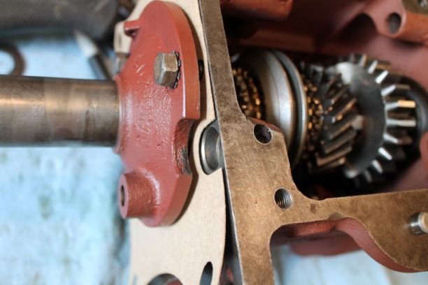
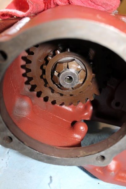
You are attempting to adjust the slop of the front blocking ring by adding or moving shims on the rear output shaft. The procedure above mentions using clamps to hold the rear bearing in place. On the advise of a friend, I installed the rear transfer case, with gasket, the gear and togqued the castelated nut down to tighten everything up as it would be in final assembly.
You will end up assembling and measuring several times (11 for me) to get things just right. I used the original rear bearning and honed the inner race just enough so that it "sliiped" on the shaft. This made repeated assembly easier in that I did not have to press on and off a bearing. After Everything is confirmed, you do one final assembly by pressing on the new bearing and use a new gasket as well.
More on Setting the Slop in the Blocking Rings
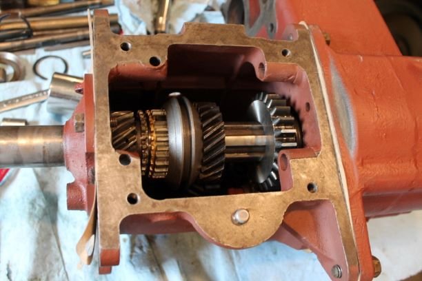
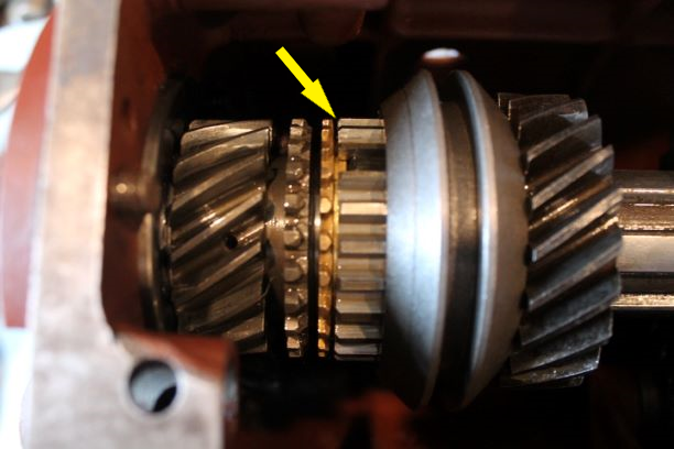
With everything in place and torqued down I compared the slop between the two blocking rings and made sure they would freely rotate a few degrees on their respective cones. They do rotate, the two shafts will rotate independently when in neutral, but there is a difference between the spacing of the rings.
.
The front ring has a good bit of clearance.
The rear ring is very tight and will barely move fore and aft, but it does rotate.
Using a feeler gauge, I can measure between the clutch hub and the blocking ring. I get 0.044" in front and 0.017" at the rear. A difference of 0.027".
From what I understand, the rear clearance is fixed and cannot change. What you are attempting to do is to adjust the slop in the front blocking ring so that it closely approximates the rear ring.. The front clearance can be decreaced by adding special shims, or increased by removing thickness of the spacer, or eliminating the oil baffle (which is not needed with sealed bearings)
Goal for the day: Add shims on the mainshaft to equalize slop between two blocking rings.
Outcome: Adding 0.025" of shims made it so tight that neither blocking ring would rotate freely and there was no slop in either ring. The two shafts would not spin freely in neutral indicating too aggressive use of shims.
Decision: I consulted with my friend who knows T84s. We had a long conversation and he believes that the lask of slop in the rear or 2nd gear blocking ring is troubling. I measured its length of the 2nd gear and found it to be 1.352" The tolerance should be between 1.340" and 1.353". That places this in the almost too long category and has made the blocking ring really tight. It's a CROWN gear. The original, which is pitted is 1.342". I'm going to call the vendor and see what he says.
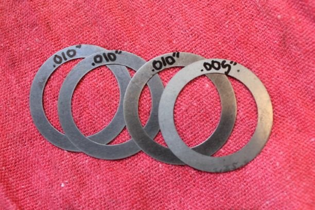
Here are the shims from the kit.
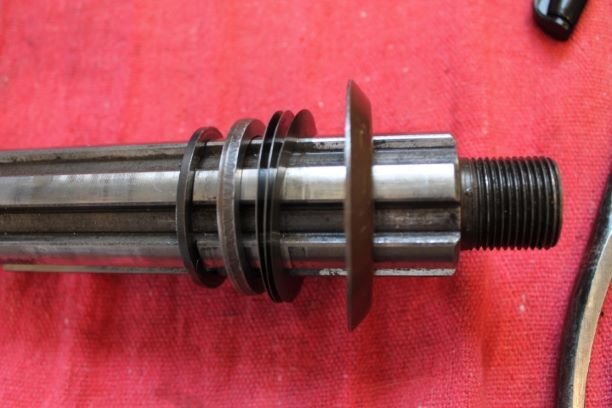
Here they are fitted onto the shaft before assembling everything together as before, yet again
Just a note I found it easier to lay the two cases as shown to get the rear bearing to "slide" into the transfer case bearing recess. I used some slight taps with a rubber mallet to coax the transmission down. Just be careful not to introduce side loads as the bearing will enter the recess off angle and make it difficult.
Repeated Attempts to get the Right Slop
In a post above I used 0.025" of shims in an effort to reduce the front blocking ring slop and found that it made things too tight.
On the next attempt attempt, I used 0.010", or one of the thick shims from RFJP, and tested everything. It did improve things quite a bit. The slop between front and rear blocking rings are not exactly the same, so I will make another shim adjustment after consulting with a friend. He advised using 0.005" shim. That seemed to do the trick.
The video below demonstrates the verification of the following:
1. When in neutral, both shafts turn independently of one another ie. no binding.
2. The gap in front of and behind the clutch hub shifting plates GPW 7116 (dogs) are fairly consistent with slight variations
3. When alternately in 2nd and 3rd gear, the blocking rings are free to rotate and the "slop", fore and aft, is approximately the same, just a bit tighter on the rear ring.
4. All gears (Rev, Lo, 2nd and 3rd) engage properly and allow the transfer of rotation to the output shaft in the appropriate manner.
Final Assembly
It has been several months since I finished the transmission and my documentation has been lacking. Il post as best as I can what I did to finish it up. Here is the detail from the TM
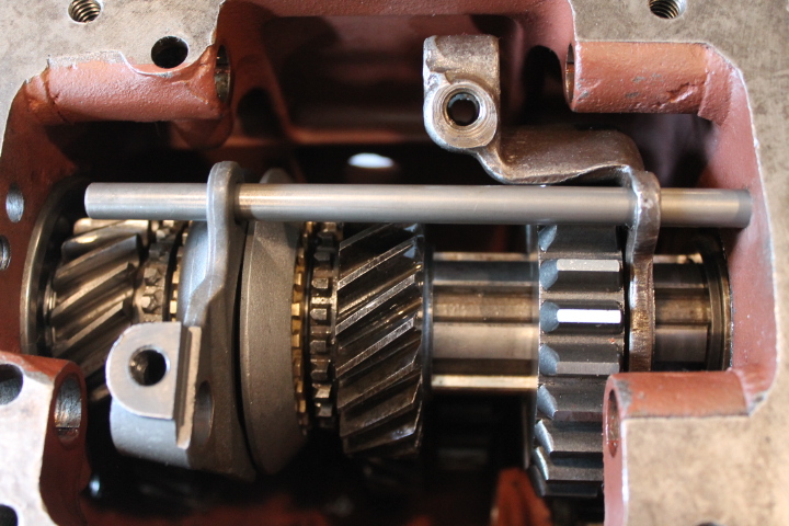
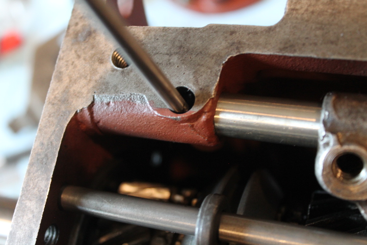
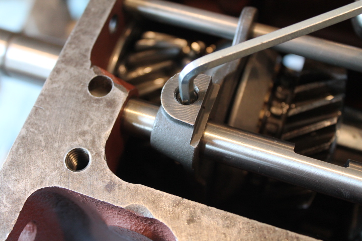
f. Install First and Reverse Shifter Fork. Hold the first and reverse shifter fork in position on the first and reverse gear, and slide the low and reverse shifter shaft (short shaft) into the case about half way. Drop an interlock spring and ball in the pocket Press down on the ball and push the shifter shaft all the way in the case. Line up the groove of the shaft with the shifter fork and install the lock screw.
g. Install Second and Third Shifter Fork (fig. 8). Repeat the same procedure as used in installing the low and reverse shifter fork, and then push the guide rail into the case and through both shifter forks.
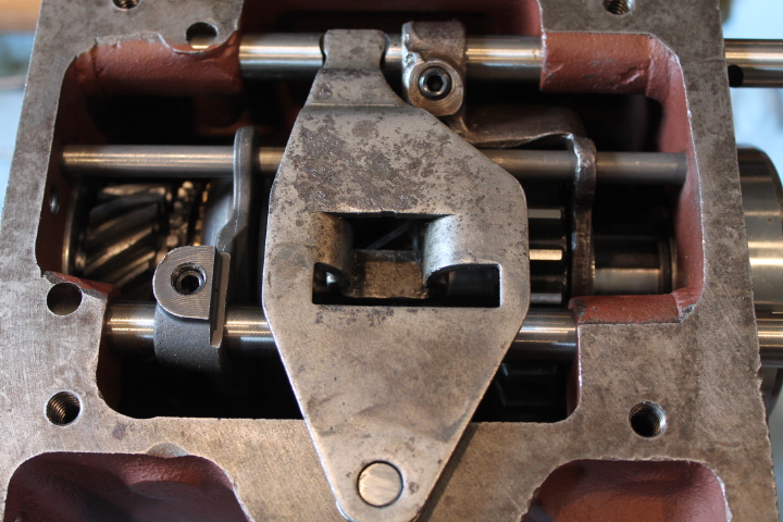
h. Install Gearshift Housing on Case (fig. 17). Place the transmission in neutral position. Lay the shifter shaft plate on the pivot and on the shifter shafts. Lay the spring washer on the pivot. Place a new gearshift housing gasket on the case. Place the shift lever in neutral position. Lay the housing on the transmission and install the four lock washers and cap screws in the housing
i. Install Clutch Release Bearing (fig. 3). Slide the clutch release
bearing assembly onto the main drive gear bearing retainer and install the clutch release bearing return spring.
