GPW Springs
BEFORE
AFTER
Front Spring Pack Tear Down
Taking the Spring Packs apart is essential to properly restoring them. The rust and grime that builds up between them MUST be removed or you will quickly regret not doing it when they are apart.
There are a few considerations:
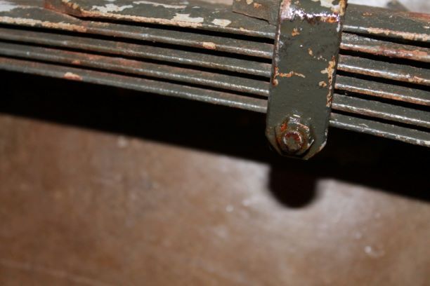
- The bolts that connect the spring clips are quite delicate and subject to much abuse and damage and they are typically rusted to the point of making them unusable. The ones on this pack had been ground down to the point where no wrench could be fastened to them. Unfortunately these F marked bolts could not be saved with my skills so I ground them off.
- The spring clips themselves tend to get worn on the bended edges and if separated they can break easily. Fortunately NOS clips are readily available as are the rivets. They are not that expensive.
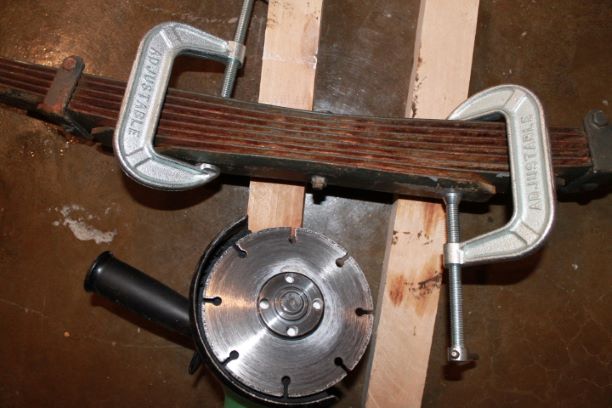
- When taking the pack apart, some of the springs are assembled with tension as the center bolt nut is tightened down. Only take them apart when properly clamped to avoid them springing apart. I just used two heavy metal clamps.
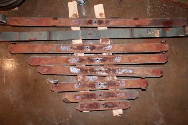
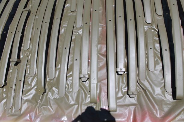
The tear down was straignt forward, and from the images you can see the amount of rust and debris between the original springs. Whith them taken apart, I can gt new clips and rivets ready and use grade 8 hex head screws with the logos ground flat to imitate vintage screws. I do not think you can find original or reproduction screws for the spring clips.
Cleaning up the Individual Springs
I spent a few hours at the sand blaster company getting several parts cleaned up. I took springs, hubs and brake backing plates among other things.
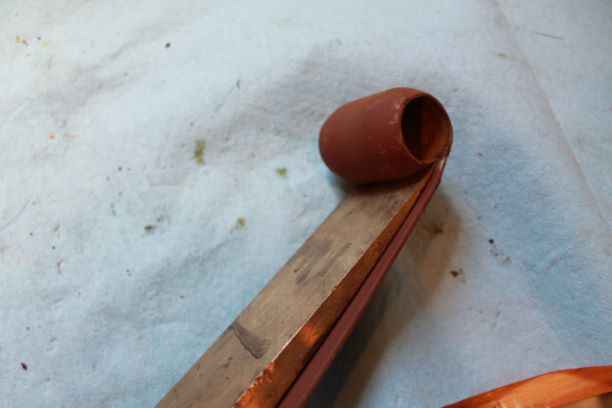
After blasting the springs, i primed them using Rustoleum Rusty Metal Red Oxide Primer. I began taking out the old bushings as well. The old copper ones will press out and the threaded metal bushings come out by expanding the eye with a brass wedge and using a 7/8" wrench to thread them off. I'll paint them with OD before putting in new bushings and honing those to size if required.
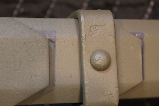
I had one worn "C" clamp and am awaiting the 1/4" x 9/16" solid steel round head rivets to install an NOS clamp. It is nicely marked with the F logo. I will make sure the Left and Right springs go back on the proper side as the front Left and rear Right eyes are supposed to accept the Left Handed Threaded bushing. The others, and the eyes on the frame receive the Right Hand threaded bushings.
Replacing Broken Spring Clip
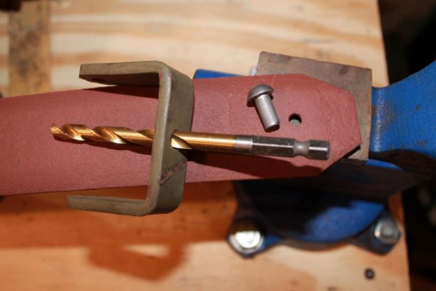
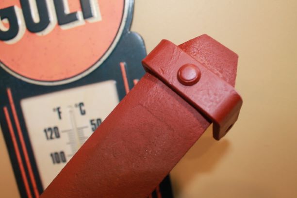
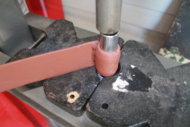
Replacing the spring clips is fairly straight forward. I used a 1/4" drill bit to reshape the hole in the spring to receive the rivet. I test fitted the clip, spring and the 1/4" x 9/16" solid steel dome shaped rivet. I used a propane torch to heat the rivet cherry red and placed it into the hole upon the flat surface of my vice. I used my air hammer and a domed shape anvil to squash the rivet down.
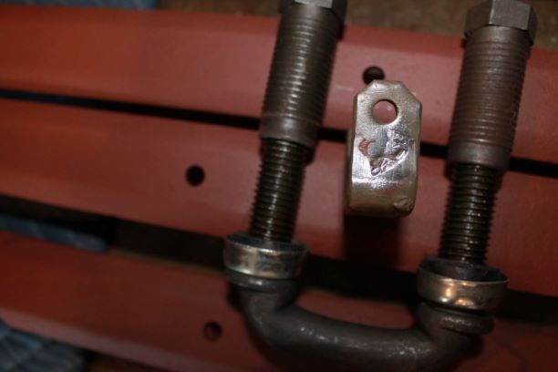
As you can see from the image, the anvil I used was a bit too small and left an indent in the head of the rivet. I will purchase a larger diameter anvil for the air hammer. The key is getting the rivet on tight so that nothing moves.
Final Painting
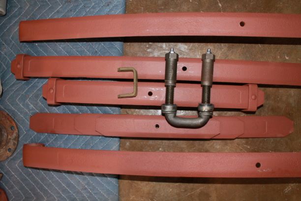
Before painting the springs I removed the remaining bushings that were still in a few of the No. 2 springs. For the bronze bushings a 13mm socket worked well and for the threaded bushings, a 14mm was suitable. The use of a brass wedge under the eye expanded them slightly and allowed them to press right out. I will use that for assembly as well.
Once that was done I cleaned the small bits of grime that was missed during sandblasting. I re-primed any scratches and gave everything two coats of OD. I will not spray on plastic again as the paint tends to get tacky in the sun and wants to peel off onto the springs. That made for additional work. I will use some metal racks next time.
Slip Plate
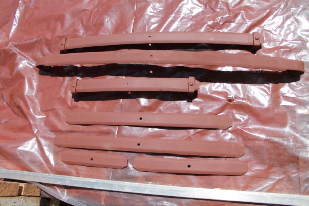
On the G503, there was a discussion regarding how to prevent wear and noise between the spring leaves. I initially considered some form of graphite as was originally used, but that quickly dissipates and leaves a black runny mess on the springs. Others recommended a form of tape, but that would quickly abrade and potentially be a source of moisture retention. One member posted a product called Slip Plate. His testimony was convincing so I purchased a can, which is available on most any paint or automotive site. I am using 12oc can of spray.
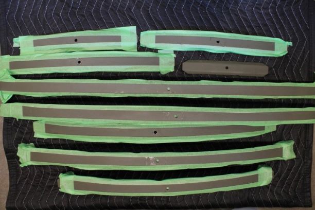
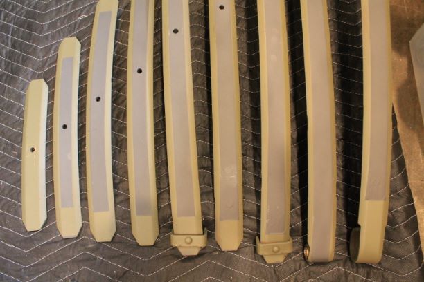
I cleaned the surfaces of the OD painted leaves and then masked off the convex surface of the leaves along the beveled edge that will come in contact with the adjoining leaf. I did not bother to mask the 45 degree areas as those will get another shot of OD after assembly. The wear patterns on the convex surface are easy to see and serve as a guide for applying the masking tape.
Painting is as with any spray paint. The graphite solution is embedded within an enamel emulsifier that dries like paint when applied. According to the man who posted on the G, he has over 1200 miles on his springs with no issues. I will let it dry for a day before assembling the springs.
The last image on the right shows the finished product. If you rub your finger on it it gets shiny and looks like the graphite from a pencil. We'll have to see how durable this is.
Assembly
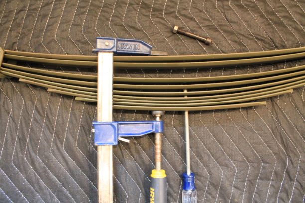
I took the 9 springs from the rear section, mated them together and placed a No. 1 Phillips screwdriver through the center hole to line them all up. With the screwdriver in place, I used a screw clamp to mesh the springs together. Once they were sufficiently compressed, I inserted the center bolt and tightened down the nut. No lock washer is needed as the spring expansion keeps the nut on tight. Note the screw head goes on the concave side of the No. 1 spring and that will sit in the recess of the footer on the axle.
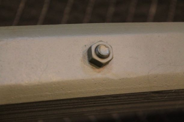
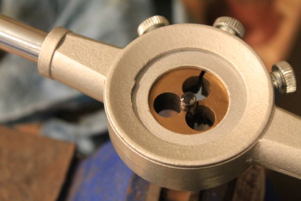
With the nit securely attached, I toughed everything up and took an opportunity to chase the threads on the 1/4" spring clamp screws. I am fortunate to have 16 from various springs and will install them on 14518. These are very hard to find with the F logo on them. I don't want to take the chance of damaging them. Three more springs to go.
TM notes on Spring Installation
a. Description and Data.
(1) Description. The front and rear springs are the semi-elliptic type. The front end of the front springs and the rear end of the rear springs are shackled, using the U-bolt type shackle with a threaded core bushing. The rear ends of the front springs and the front ends of the rear springs each have a bronze bushing and are each pivoted by a pivot bolt mounted to a bracket
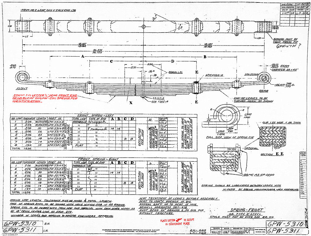
on the frame. A torque reaction spring, mounted on the left front spring, stabilizes the torque of the front axle. The front springs appear to be identical in construction but are different in load carrying ability. The left spring can be identified by the letter “L” stamped on the No. 8 leaf.
(2) DATA.
Front spring:
Make Mather
Type leaf Parabolic
Length (center to center of eye) 36¼ in.
Width 1¾ in.
Number of leaves 8
Front eye (center to center bolt) 181/s in.
Rear eye (center to center bolt) 18 1/a in.
Left camber under 525 lb ·~ in.
Right camber under 390 lb 6 in.
Rear eye Bushing
Rebound clips . 4
Rear springs:
Make Mather
Type leaf . Parabolic
Length 42 in.
Width 1¾ in.
Number of leaves 9
Rebound clips 4
Camber under 800 lb ¾ in.
Eye to center bolt 21 in.
Front eye Bushing
D. INSTALLATION:
1) Place the front spring with the bushing end in the spring bracket on the frame. Insert the spring shackle bolt in the spring with the grease fitting facing outward. Install the nut and cotter pin on the shackle bolt. Raise the forward end of the spring and insert the spring shackle in the bracket on the frame and in the spring. Install the spring shackle bushing with the grease fittings facing outward. Place the spring U-bolts in position on the axle. Place the spring seat plate on the U-bolts. Install the the four nuts that secure the U-bolts to the axle housing. Install the lower end of the shock absorbers to the spring seat plate. Apply specified lubricant to all fittings.
NOTE: There are 4 U-shaped spring shackles. Two of the shackles have one right handed thread and one left handed thread. The other two have all right handed threads.
The shackle mounts that are riveted to the frame of the GPW all receive a right handed thread. The two left handed thread ends of the shackles go in the LEFT FRONT spring eye and the RIGHT REAR spring eye.
The embedded video at right is a good tutorial for installing the springs. Pay attention to the order of assembly with regard to springs, axles, wheels etc. If you install the wheels, you have more weight to move around to lift the springs up to the shackle mounts. Another way is to install the springs and shackles, then place the axle in place on the springs without the wheels attached.
Front Spring and Torque Reaction Spring Assembly
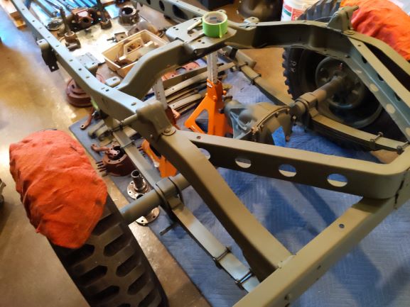
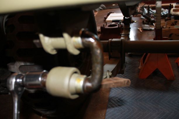
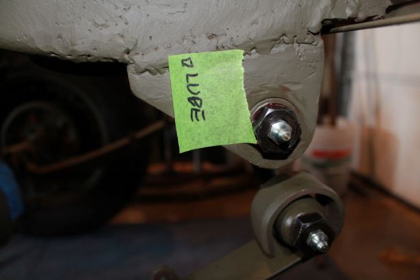
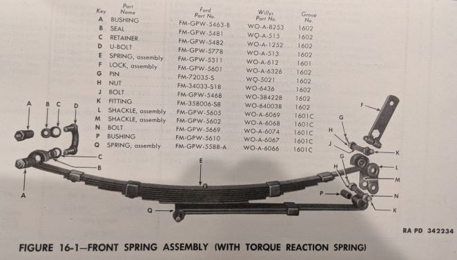
The assembly of the two spring packs was as simple as with the rear springs. Having never done a front axle on a GPW before, and having an older TM, I found a bit of on-line help regarding the installation of the Left Front Spring with the Torque Reaction Spring (TRS).
From what I understand, the best way to assemble the left side spring pack with TRS is to install the rear shackles and bolts first, and then fit them to the axle as with the other springs. Here are the steps I used to successfully and without much effort, install the TRS spring pack:
- Raise the front of the frame to about 24" and place jack stands under the left and right side frame rails behind the spring mounts.
- Install the rear spring eye onto the rear spring mount. Insert the bushing into the eye, thread the upper shackle bolt through the outer shackle, then through the mount and rear eye, and completely through the mount to the other side. Install the inner shackle and install the bolt finger tight.
- Install the rear eye of the TRS onto the lower shackle. Insert the lower (shorter of the two bolts) through the outer shackle, through the eye bushing and through the inner shackle. Install the castle nut finger tight.
- Roll the axle into place over the spring which has the front eye resting on the ground and the front of the TRS under it on the ground.
- Raise the front eye of the spring to the shackle, maneuvering the axle into place so that the bolt head recess is above the center spring bolt head.
- Insert the front U-bolt through the frame and spring eye. Do not insert the threaded bushings yet.
- Slip the large U-bolts over the axles.
- Raise the TRS up ensuring the center bolt goes into the center bolt hole of the TRS and slip the two bolt ends of the U-bolt into one side of the TRS. Install the bolts finger tight. You may need to use a clamp or ratchet strap to raise the TRS up far enough to get the U-bolts into the holes. A heavily arched spring will make this more difficult. Mine were very easy and a long clamp worked fine to hold the TRS in place.
- Insert the ends of the other U-bolt into the TRS and install the bolts. Do not tighten them all the way down.
- Install the front spring eye u-bolts bushings and tighten them
- NOW tighten the bottom bolts of the axle U-bolts.
- Tighten all shackle bolts castle nuts and install the cotter pins.
- Install the lock assembly.
- Insert the grease fittings.
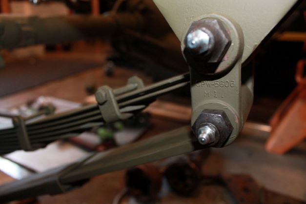
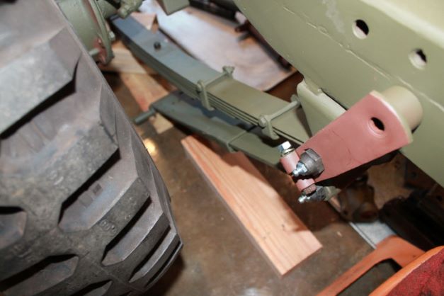
Schock Absorber Installation.
I am using a set of reproduction GPW shocks that came with another project. I am not sure where they were purchased from but they are stamped correctly and seem to fit nicely. They came with 16 rubber bushings but no cotter pins. They were painted a shiny OD so they received a nice coat of 33070 to match the rest of the parts.
You only need 8 of the special Shock Absorber Washers 356525 and these go on the outside of the shock bushing to press against the rubber as you install the cotter pin.
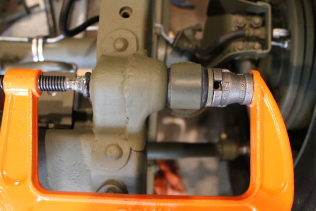
The frame upper shock pin has a flat surface to contain the rubber bushing on the inside, and the lower inner bushing will seat against the welded washer that is on the spring bolt mounting plate.
I copied one of the many compression tools using a simple pipe adapter. I cut two grooves into the one end so that I could insert the cotter pin through the groves and into the pin hole. Using a C-Clamp, I was able to compress the washer against the rubber bushings and insert the pin. I was able to do all 4 shocks with the wheels attached.
