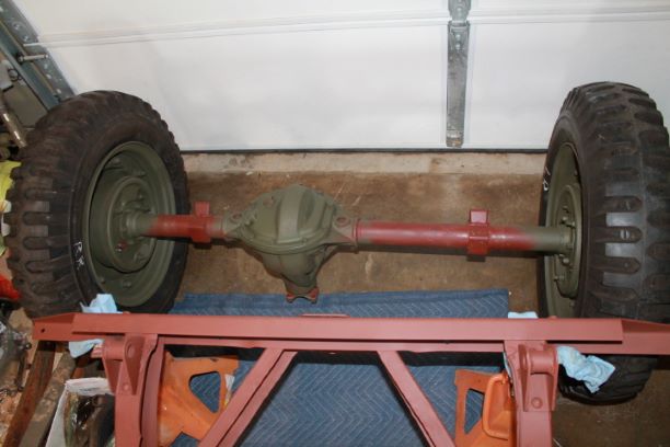
14518 Rear Axle
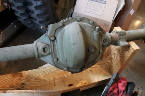
BEFORE
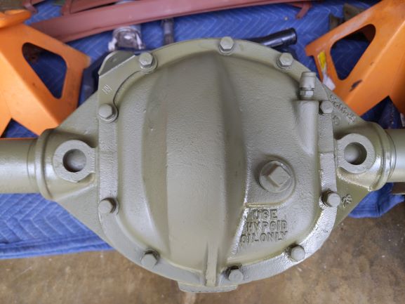
AFTER
Tear Down Begins
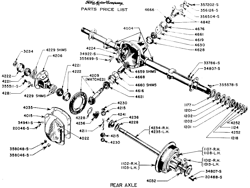
I began the tear down of the rear axle. Removal of the rear cover allowed me to do a quick assessment of the interior parts. The pinion egar teeth are heavily pitted so I will replace the pinion and ring gear as they are supposed to be a mated set.
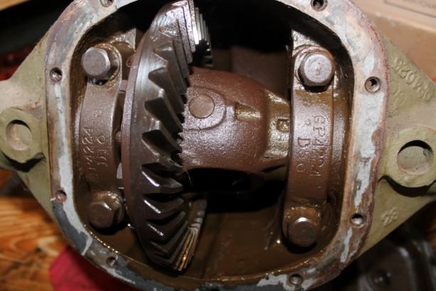
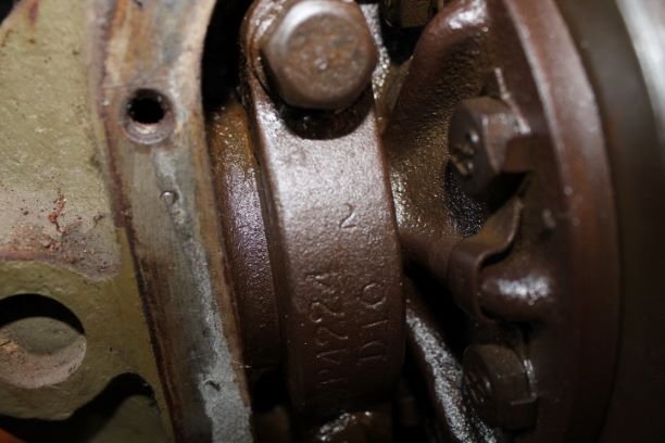
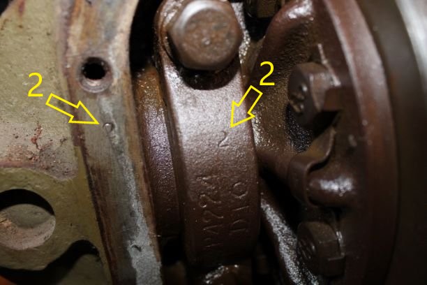
The bearing caps are stamped with a "2" on one end of the cover near the bolt. On the long axle side they are oriented vertically, and on the short axle side they are horizontally. No need to punch mark these. This will help in orienting the correct caps during assesmbly.
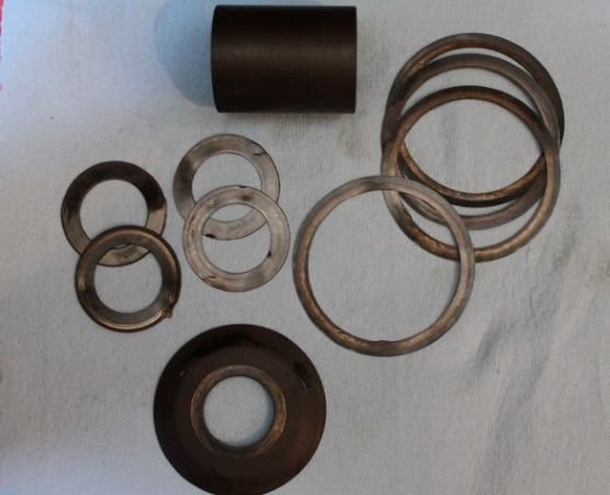
I removed the rear pinion and recorded the shim sizes. I failed to measure the pinion depth to see how close it was. WIll have to start from scratch anyway. The shims and oil slinger are nicely script "F" marked.
Small Diameter shims (rear pinion bearing):
GPW 4659B 0.005" 2 ea
GPW 4659D 0.030" 2 ea
Large diameter shims (rear pinion bearing)
GPW 4660B 0.005" 1 ea
GPW 4660C 0.010" 3 ea
Inspection of Rear Axle Components
From the TM:
a. Cleaning. Clean all parts in dry-cleaning solvent. Rotate the bearings in dry cleaning solvent until all trace of lubricant has been removed. Oil the bearings immediately to prevent corrosion of the highly polished surface.
b. Inspection and Repair.
(1) Axle Housing and Cover
(a) Inspection. Replace the axle housing if it is broken at any of the welds or if it is cracked or bent. Replace the drive pinion bearing cups if they are pitted, corroded or discolored due to overheating. Replace the oil seals in the axle housing regardless of their condition. Replace the differential cover if cracked or it has damaged threads in the filler hole. Replace the breather cap on the cover if it is missing or damaged.
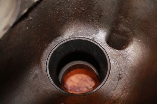
(b) Drive pinion bearing cap replacement. Remove the inner and outer bearing cups using a standard puller. To assist in assembly, note the thickness of shims when removing the inner bearing cup. To install a new bearing cup, use a brass drift and hammer. Place the original thickness of shims behind the inner bearing cup and tap the bearings cup lightly around the entire circumfrence of the cup until it is flush with the shoulder in the axle housing.
(2) Drive Pinion Assembly. Replace any roller bearings that are pitted, corroded or discolored due to overheating. Replace the drive pinion gear if it is excessively worn or broken teeth or if the splines are worn or the threads damaged. The differential gear and the drive pinion are furnished in matched sets only, and if either is found damaged, both must be replaced. Small nicks can be removed with a fine stone.
(3) Differential Assembly. Replace any gears that are excessively worn or have any missing teeth. The differential ring gear and the drive pinion are furnished in matched sets only, and if either is found damaged both must be replaced. Replace the differential pinion gear if the inside diameter is more than 0.625". Replace the differential pinion shaft if the inside is worn to less than0.625". Replace the axle gear if the hub is worn to less than 1.500". Replace the differential pinion gear and the axle shaft gear thrust washers if the thickness is worn to less than 0.032". Roller bearings and cups that are pitted, corroded or discolored due to overheating must be replced.
(4) Axle Shaft. Replace the axle shafts if they are bent or have any worn or broken splines.
To the right is a short video on preliminary wear inspection for the gears. I found the same problem with the bolts being loose. I plan on removing the lock tabs and using RED Locktite.
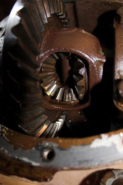
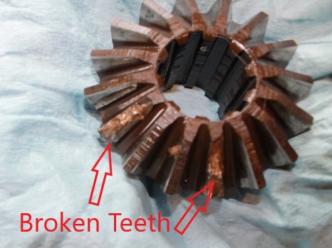
Below the video is a series of pictures of the spider gears. After seeing the video that someone posted, I decided to take another look at my spider gears and when I rotated them all at least 360 degrees and looked at all four gears I found one of the gears had two severely damaged teeth.
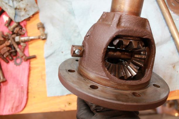
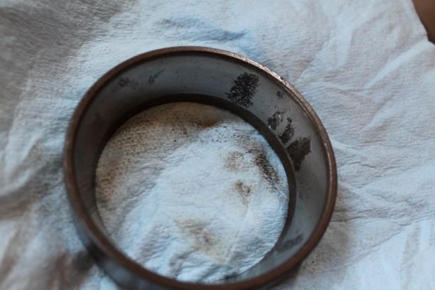
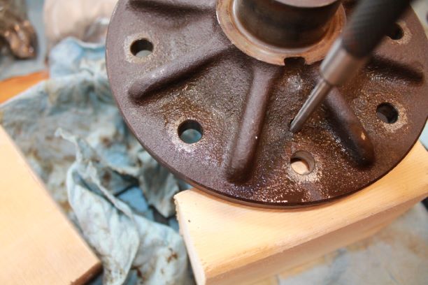
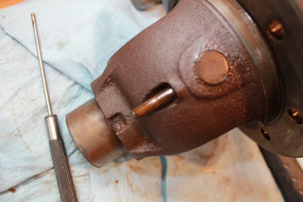
I decided to replace the spider gears, pins and thrust washers as a kit. To the right are four images showing the removal process. Use a long solid drift pin to drive out the smaller rin (which may be a split pin, roll pin or tapered pin. you must drive it out the correct way or you may cause damage.
The larger pin comes out with a ight rap from a hammer on a brass drift, and if you rotate the cluster 90 degrees you can remove the two gears with the convex washers, followed by the two remaining gears. This will be $100-ish well spent.
Assembly of Rear Axle Components
TM:
a. Install Inner Bearing on Pinion. Press the inner
bearing on the pinion, using an arbor press. Make sure the bearing
is firmly seated on the shoulder of the pinion gear when installed.
Oz:
I own a small hydraulic press from Harbor Freight that will do 6 tons. I used that to press on the inner bearing. It is a simple process.
TM:
b. Adjust Pinion in Housing . Place the pinion in the
differential housing. Install the gage 41-G-176 to check the setting
from the back face of the pinion to the center line of the differential case bearing. The standard setting is 0.719 inch. If the gage reading is more than 0.719 inch, shims will have to be added to the inner bearing cup (par. 32 b). If the reading is less than 0.719 inch, shims will have to be removed from the inner bearing cup (par. 32 b).
Oz:
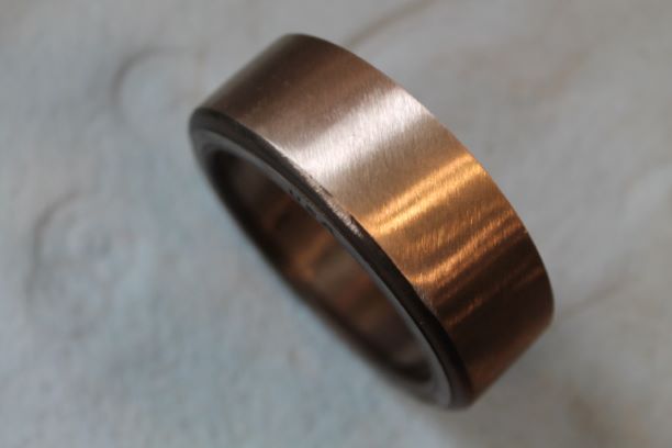
This process might have to be done several times to get the depth just right. To make the process easier, I reduced the outer diameter of a used cup enough to provide a slip fit of the cup in the housing. This way I won't have to pound the cup out multiple times and ruin the shims.
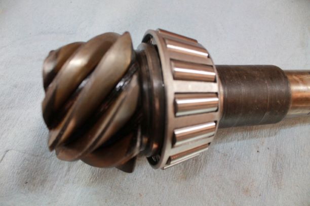
I also have a flat plate made to measure the depth of the pinion. As you can see it goes under the caps and using a depth gauge you can ensure the pinion is seated at 2.250" below the centerline of the axle shafts. There is a bit of simple math here which I'll explain below. The cap screws are torqued to 50 ft.lbs.
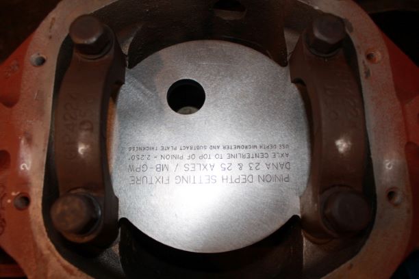
Measuring the Depth of the Pinion
Oz:
Continuing from step (b) above: First I measure the total length of the shaft of the depth gauge when fully extended and the needle reading 0.000". I insert the depth gauge through the hole in the flat plate and allow it to rest on the top of the machined surface of the pinion. As I push the gauge down I notice the total movement of the needle reading on the gauge. This gives me the displacement. I then subtract this number from the total length of the gauge to get the depth of the pinion from the TOP of the plate. Since the bottom of the plate is at the center level of the axles, I have to subtract the thickness of the plate (0.375") from my reading to get the pinion depth. The Dana 23 is supposed to be 2.250" below the plate.
Here are my three sets of calculations (The first set of numbers has different readings because I did not fully screw in the threaded shaft cap.)
Reading No. 1 2 3
gauge lgth: 3.043" 3.018" 3.020"
(-) Needle reading: 0.393" 0.371" 0.371"
(-)Plate thickness: 0.375" 0.375" 0.375"
Pinion depth: 2.275" 2.272" 2.274"
Average depth: 2.2736"
Since the pinion is deeper in the recess of the differential, I will need to raise it up by adding shims under the bearing cup. I'll add .025" worth of shims to the bottom of the cup to get the pinion to the required depth of 2.250"
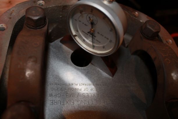
YouTube Video posted by another restoration specialist that I found helpful in understanding how to use the Pinion Depth Measurement Plate.
Adjusting the Depth of the Pinion
Oz:
Now that I know that I need to add 0.025" worth of shims under the bearing cup I can begin on the next step. I removed the bearing caps and the plate and took out the pinion. Since the bearing cup was milled to a smaller outer diameter, it came out easily. I measured several shims from my inner bearing cup shim pack and selected the closest combination to 0.025" I placed those under the cup, then seated the cup on top of the shims and drove it in to ensure it was properly seated. I added the pinon and depth gauge plate and torqued the cap bolts to 50ft-lbs again. I then took 3 separate measurements to verify my work. The calculation method is the same as above, only with different numbers due to the shims.
Here are my three sets of calculations
Reading No. 1 2 3
gauge lgth: 3.016" 3.016" 3.013"
(-) Needle reading: 0.393" 0.392" 0.393"
(-)Plate thickness: 0.375" 0.375" 0.375"
Pinion depth: 2.248" 2.249" 2.245"
Average depth: 2.2473"
That is pretty close to 2.250" (assume the preload may pull the pinion into the cap slightly resulting in a closer number. I should perhaps find a different shim pack so that I can get it right at 2.250"
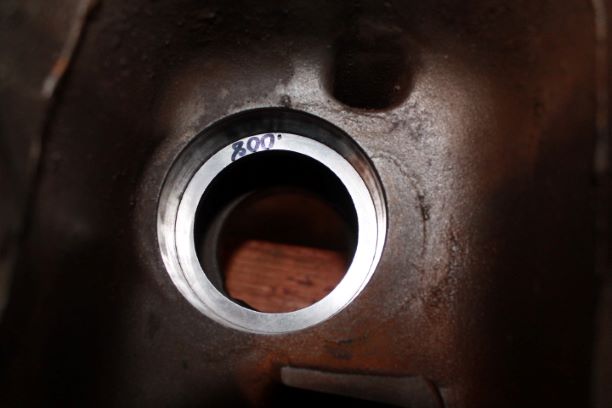
Adjust the Outer Bearing "Preload"
TM:
d. Adjust the Outer Bearing, Place the universal joint flange on the pinion. Install the nut on the pinion and draw the universal joint flange down tight. Turn the universal joint flange. If there is a slight drag, the pinion bearing adjustment is correct. If the pinion turns with difficulty or cannot be turned by hand, shims should be added behind the outer bearing. If the pinion is too loose, shims should be removed. Remove the universal joint flange and add or remove shims unitl the correct adjustment is obtained, again remove the universal joint flange and install the oil seal on the pinion. Install universal joint flange. Install the nut and cotter pin.
Oz:
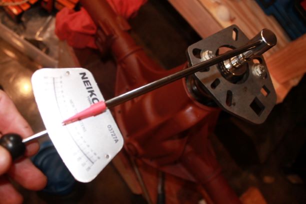
The TM is very vague here when refering to slight drag. The Jeep manuals for later models use 12-20 INCH pounds. I checked that with a bar gauge. I do noat have a dial inch pound gauge.
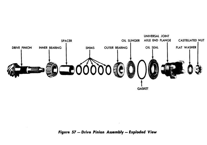
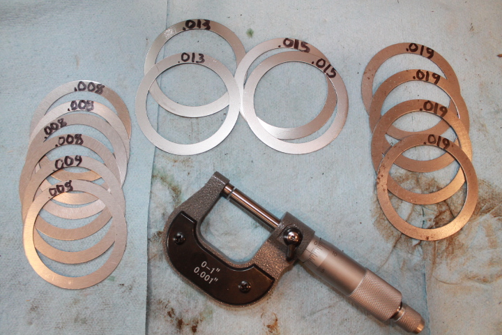
To begin with, I used the same thickness of shims as were originally installed under the outer bearing (0.072") The shim pack I have only has 0.008" shims, all measured with a micrometer. That is 9 shims. I installed the pinion and other components as shown in Fig. 57, leaving out the oil slinger, gasket and oil seal. Those will be added when I am completely done with the gear pattern adjustment.
My first attempt resulted in about 5 inch pounds, or too loose. I removed one 0.008" shim leaving 0.064". Here is where having a set up bearing comes into play. I had a machinist take the ID of a new bearing down a bit so it would slip on. This way I do not have to press on and off a bearing for each of the many adjustments. It took me 6 tries to get it right. I will keep the set up bearing for other axles and replace it with a now bearing that will snug down tight when the final assembly happens.
Second attempt with 0..064" resulted in too tight 30 inch pounds. It seems I needed a combination between 0.072" and 0.064". Over the next four fittings, I ended up cleaning the end surfaces of the spacer and taking them down by about 0.002" and I used one of the old thicker F-marked shims to arrive at a combination of 0.068". The final reading on the bar meter was 12 inch pounds, which is at the lower end of the specification. I'll leave the set up bearing on (and the set up inner bearing cup) until I get my final tooth pattern and backlash correct.
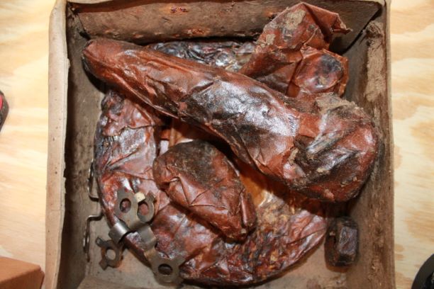
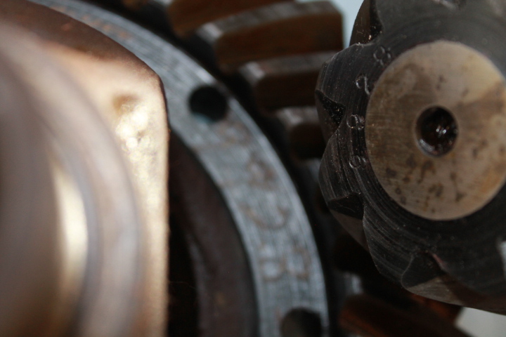
With this step done I turned to the NOS ring gear. Here is an image of how they were packed in WWII. Cosmoline, wax and wax paper. I used a heat gun to remove everything. It took about an hour to get it all cleaned up. Notice in the final image, the engraved number on the ring gear matches the stamped number on the end of the pinion (9928). THIS IS A MUST as they are machined together as a matched set.
Differential Case Installation
TM:
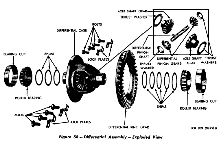
e. Install Gears in Differential Case. (Fig. 58) Place the axle shaft gear thrust washers on the two axle shaft gears. Place the axle shaft gears in the case. Place the two differential pinion thrust washers and gears in the case. Install the differential pinion gear shaft that secures the two differential pinion gears in the case. Install the pinion shaft lock pin in the case.
f. Install Differential Ring Gear. (Fig. 58) Place the differential ring gear in position on the case. Install lock plates and cap screws that secure the ring gear to the case. Bend the ears of the lock plate on the cap screws.
Oz:
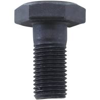
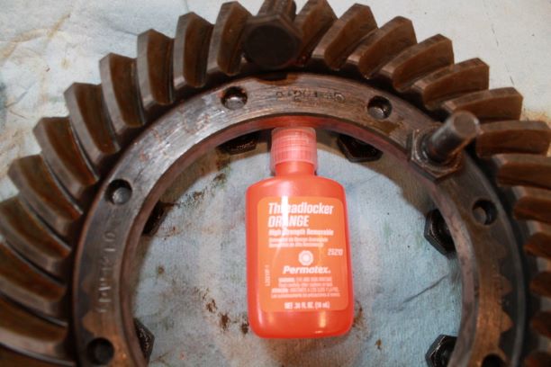
. I have read many articles on the cap screws and locking plates. Most everyone says to use new Grade 8 bolts and lock tight instead of NOS bolts and locking plates. On every one of the 8 bolts that I took off of the old ring gear, they were either finger tight or only took a small bit of torque to undo. The ears of the lock plates were easy to break off. I dont want that trashing out another pinion. I ordered new spicer grade 8 bolts (YSPBLT-008) These are grade 8 and made specifically for the older Dana 23/25/30 differentials.
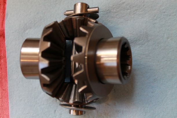
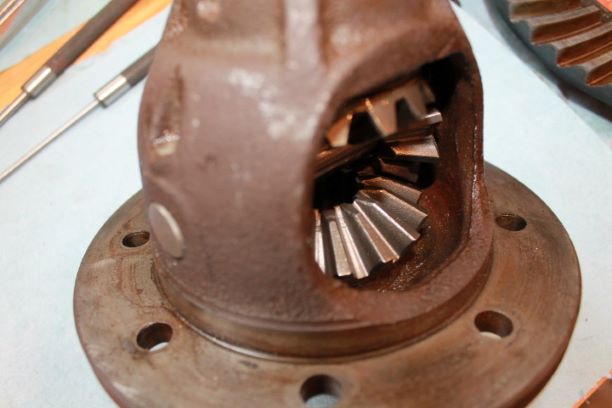
As posted earlier I ordered a new set of spider gears, pins and thrust washers. Those are really easy to install. Just make sure you put the small pin in from the gear side of the case as this particular kind is tapered.
I used some pre-lube on all the gears, the large pin and the thrust washers to keep rust away while the rebuild continues.
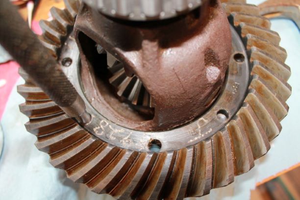
When installing the ring, it fits tight over the housing and if you do not start alligning the bolt holes, you will ahve a hard time getting the screws in. If that is the case start over. You don;t want to cross thread the holes or screws. Use a thick punch to help allign things as you lightly pound (rubber mallet) the ring into place. You don't have to go all the way down, just enough to begin seating the screws. When tightening it will pull the ring gear in place, just do opposite screws a few pounds at a time to keep from warping the plate or damaging threads.
Install Roller Bearings on Case
TM:
g. Install Roller Bearings on Case. (Fig 68). If all original parts have been used in differential assembly, add the same thickness of shims as originally used and press the roller bearings on the case, then proceed with subparagraph h. below. If original parts are not being used, or if the original shim thickness is not known, install roller bearings on the case without shims and proceed with subparagraph i, below.
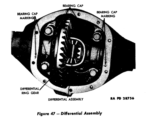
h. Install Differential Assembly in Housing. (Fig 47). Place the bearing cups on the bearings. Tilt the bearing cups in order to start the assembly in the housing. Tap the bearing cups lightly unitl the assembly is seated firmly in the housing. Install the two bearing caps so that the numbers on the caps and housing face the same way and match in every way as shown in Fig 47. (See the image I added with yellow number "2") If the differential assembly being used is not the one originally in the axle, proceed with subparagraph i, below.
i. Differential Assembly Adjustment (Fig 69). Place the differential assembly in the housing with the bearing cups on the assembly in the housing with the bearing cups in the assembly. Slide the assembly to one side of the housing. Check the clearance between the bearing cup and the housing with a feeler gauge. After this clearance has been determined ad 0.008". This will give the thickness of shims required for proper bearing adjustment. Remove the differential assembly from the housing. Remove the bearings from the case. Install the number of shims, determined above on each side of the case and install the bearings back onto the case. Tilt the bearing cups in order to start the assembly in the housing. Tap the bearing cups lightly until the assembly is seated firmly in the housing. Install the two bearing caps so the numbers on the bearing caps and housing face the same way and match in every way.
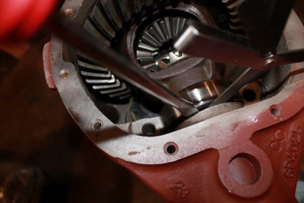
I installed the differential with cups and cones using no shims. I slid the carrier to one side and measured the gap at 0.057" It must be noted, that depending on how much pressure you put on the screw driver to create the gap will determine your measurement. I added 0.008" so used 0.065" shims, split in half that gave me 0.0325 per side. Because of the different combinations I ended up putting 0.31 on the bolt side and 0.033" on the ring gear side. After installing, and torqueing down the caps the differential gear had NO BACKLASH. I then removed 0.008" from the bolt side to create some movement. My shim pack is now 0.056" which is 0.004" thinner than the original set which had 0.030" on each side.
Check and Adjust Backlash
TM:
j. Check Backlash. (Fig 70) install a dial indicator on the differential housing so that the indicator contact is resting on the surface of a ring gear tooth as shown in Fig. 70. Rotate the ring gear back and forth to determine backlash. If the backlash is less than 0.005" or more than 0.007" remove the differential from the housing and remove the bearings from the case. If the backlash was more, the ring gear must be brought closer to the pinion. If the backlash was less, the ring gear must be moved away from the pinion. This is accomplished by removing shims, equal to the error in backlash, from one side of the case and adding them to the other side. Install the bearings on the case. install the differential in the housing.
Oz:
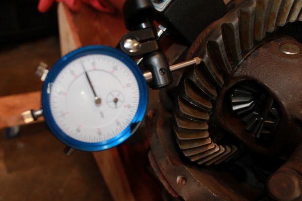
Attempt No. 2: I realize the TM says to move a shim to the other side to adjust backlash, but the carrier was in the differential so tightly that it took a 3' prybar to get it out. Since removal of the 0.008" shim produced 0.012" backlash, I will simply add a 0.004" shim back to the bolt side. That will tighten the carrier up in the races slightly and give me a smaller backlash. Forgive the blurry dial indicator, the camera was focused on the ring gear.
Attempt No. 3: That change resulted in 0.012" of back lash. Although the carrier was tight on the installation as it should be.
Attempt No 4: I switched the shim packs around leaving 0.033" on the bolt side and 0.027 on the ring gear side. That gave me a back lash of 0.007" which is right at the edge of the spec. If I change anything else, I will probably overshoot and be on the low side again at about 0.004" which I do not want.
Check Run Out
TM:
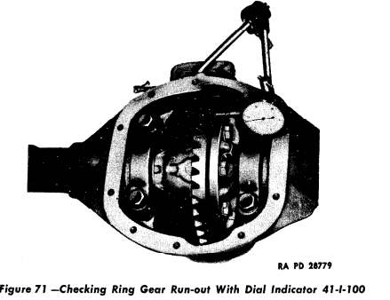
j. Check Ring Gear Runout. Install a dial indicator on the differential housing so that the indicator contact is resting on the flat side of the ring gear. Turn the pinion drive flange by hand to determine the run out of the ring gear. The run out should not exceed more than 0.003". If the run out exceeds 0.003", remove the differential assembly from the housing and remove the ring gear. Check the surface o the ring gear or chips or small nicks that might have occurred during assembly. I any are found remove them with a fine stone, also check 1+ the angle on the case or being sprung. Reinstall the assembly in the housing and recheck.
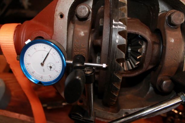
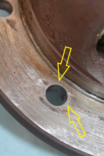
OZ On my first attempt I had readings from +0.005" to -0.002". That is a total run out of 0.007". I marked those on the ring with chalk. You can see the - II on the ring gear indicating 0.002" below 0 run out. The TM states 0.003" and apparently the CJ manual allows a runout of 0.006". I will shoot for the smaller figure and accept the larger, but not 0.007". I removed the ring gear from the carrier and found that all of the lips where the bolts protrude on the carrier surface were slightly raised. Although the holes for the bolts on the gear's mating surface are beveled, I am guessing that this uneven surface is the source of some of the problem. I used a fine flat honing stone to take the surfaces back down. Perhaps a machine shop could do better, but that would be another $25-ish and a few days of waiting. Check the images after using the stone for several minutes. Notice the area around the holes that are polished, meaning they were raised quite a bit.
Honing the carrier surface did not change anything. I reinstalled everything and checked the run out again. I am still at 0.007" run out which is 0.001" out of even the CJ specifications. . Must research what to do.
After a bit of reading and a phone call to a mechanic friend he suggested at least checking the gear wear pattern with marking paint and seeing where I am sitting. that step and results are outlined below.
I did find a suggesting that either the carrier is sprung beyond repair, or I could just accept the 0.007" run out which at the low use this will get result in only a wavering growl from the differential, or I could skim the surface by a few thou' to get things perpendicular to the axis.
I called my local machinist and he suggested I come by. After 5 minutes and $20 he took off 0.005" and created a near perfectly perpendicular surface for my ring gear to be mounted on. Here is a short video of the work. When he first started skimming, you could hear the tool noise rise and fall slightly indicating the slight deviation in the mating surface. Now it is clean and should yield about 1-3 thou run out. Upon return I do in fact have 0.0015 run out. With that I am very pleased.
Since the thickness of the gear mating surface has changed, the backlash will have changed as well, so I'll have to reset that adjustment.
Using the same procedure as mentioned above, I ended up having 0.007" of backlash with 0.024" shims on the gear side and 0.032" shims on the bolt side. Now I can go back to checking the gear wear pattern with yellow paint.
Check Gear Mesh Pattern
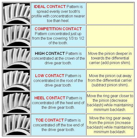
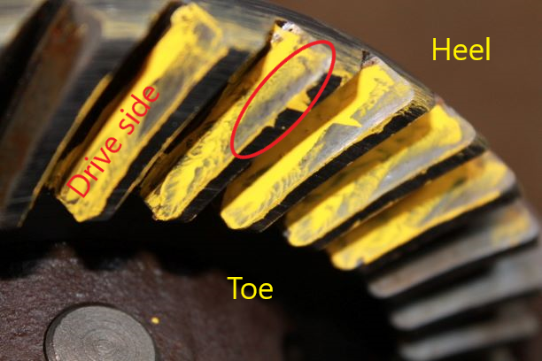
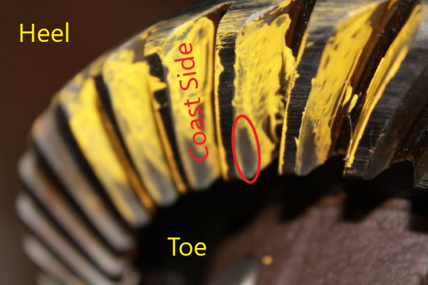
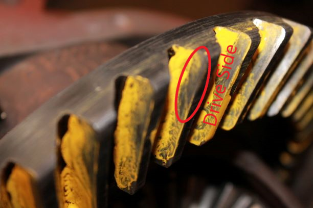
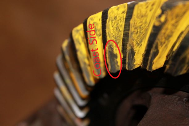
I painted the teeth of the ring gear in two opposite sides of the gear about 180 degrees out painting both the coast and run side. I ran the gear around with some pressure on the ring. Did it both directions through a few rotations. The two yellow painted tooth patterns are shown at the right. Compare this to the contact chart posted to the right.
The pattern exhibited indicates that the pinion is riding high on the ring gear teeth and therefore I need to add thickness to the shims under the inner pinion cup. I will probably use 0.003" addition under the cup. Since I am at the upper end of the backlash, I should still be in the ballpark with that measurement after adding the shim. Hopefully that will move the pinion teeth contact to the mid range below the crown and above the root. When I do this, I will need to remove a similar thickness of shims from under the outer bearing so as not to change the preload. I am currently at 12 inch pounds, so I could accept an additional increase there and still be within tolerances.
The pattern also indicates that the pinion teeth are making heel contact (outer edge of the ring gear. To correct this I need to move the ring gear closer to the pinion (decreasing backlash). Since I am at the high end of back lash, this is a good sign. Since the machinist skimmed 0.005" from the surface of the carrier, I will need to ad 0.005" to the bolt side to put things at neutral, and then move about 0.003"-0.004" from the gear side to the bolt side to keep the bearing preload the same. That should be enough to moev the run side contact from the heel toward the center or toe.
Check Gear Mesh Pattern after Skimming the Carrier
After Skimming the surface to get the run out down near zero, I repainted and tried again. I am back where I started with a pattern high on the tooth indicating a need to move the pinion deeper.
I also have a contact pattern similar to before skimming with drive side contact at the heel and coast side contact at the toe. That indicates a need to decreace backlash closer to 0.005" by moving the carrier closer to the pinion. I will add shims to the bolt side and take them from the gear side. I will try about 0.004" worth of shim transfer.
Check Gear Mesh Pattern after Skimming the Carrier
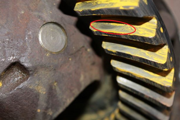
After more than a dozen different variations of pinion depth shims, getting the pre-load correct (Now at 24 in-lbs for new bearings) and adjusting the carrier shims left to right to get the correct backlash and pattern, I have what is called the competition pattern, am looking at the high side of 0.007: back lash and ended up with the following shims:
Pinion Inner: 0.044"
Pinion Outer: 0.080"
Ring Gear Side: 0.016"
Ring Bolt Side: 0.038"
I understand things may change after I press on the final bearings, but I hope it is not a significant change.
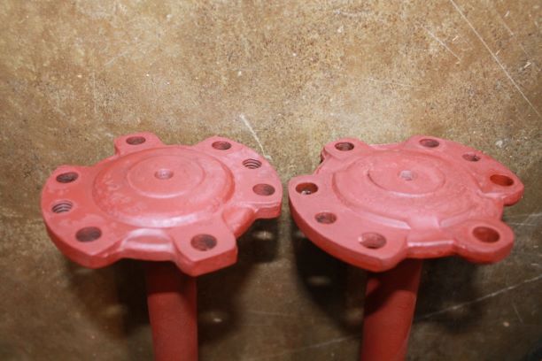
Rear Scalloped Axles
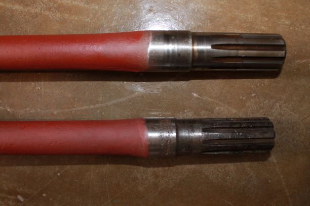
Before I finish my rear axle I took the time to examine the two rear scalloped axles that I have. These are among the hardest parts to find for an early 1942 GPW. Both are in very good condition except that the machined surfaces that ride in the inner oil seals are grooved and pitted. I have ordered a set of Speedi-Sleeves for them. This will provide a slightly larger diameter and smooth surface to prevent seal damage and oil transfer into the axle tube.
Both axles cleaned up nicely and are primed and ready for the installation of the sleeves when they arrive.
Final Axle Assembly
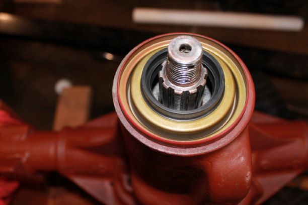
To begin final assembly of the rear axle I installed new inner oil seals. I also took the inner pinion cup from the freezer and seated onto the shim stack that I had determined earlier.
The outer pinion bearing was problematic in that when the cone was fully seated there was significant up and down play in the pinion. After hours of research and guess work I finally removed the inner pinion cup and found I installed the incorrect cup and it was too short leaving a huge gap between the two cones. Much to my embarrassment I correct the problem and everything seated nicely, although I had to change the outer shims to get the pre-load correct. After three more attempts I had the preload at 15 pounds.
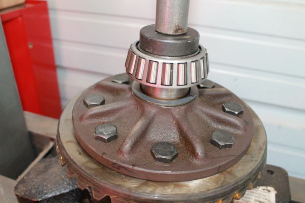
I then took off the set-up carrier bearings that were slip fit on to simplify the work of determining the proper shims and pressed on the brand new cones making sure I had the correct shims underneath as calculated above. Once the bearings were pressed on I placed the carrier back into the axle housing, installed the caps in their proper orientation and torqued the bolts to the proper tightness.
Now satisfied with all of the measurements, I took the carrier cap bolts out, coated them with thread seal and torqued them back down.
I then installed the carrier, torqued everything down and measured the run out of the ring gear. It now sits at 0.005" I am satisfied with that.
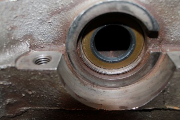
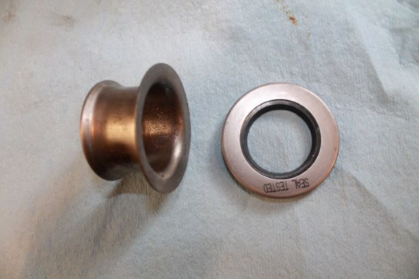
I have the new double lipped outer seal that needs to be installed. Here it is shown in the proper orientation. I coated the bottom outer edge with some grey gasket sealer. I used short section of 2" grey electrical conduit to seat the outer oil seal. It fits nicely ofer the flat portion of the seal and with a few wacks the seal was down below the lip of the housing and seated on its shelf.
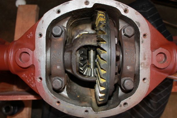
Speedi Sleeve for the Yoke
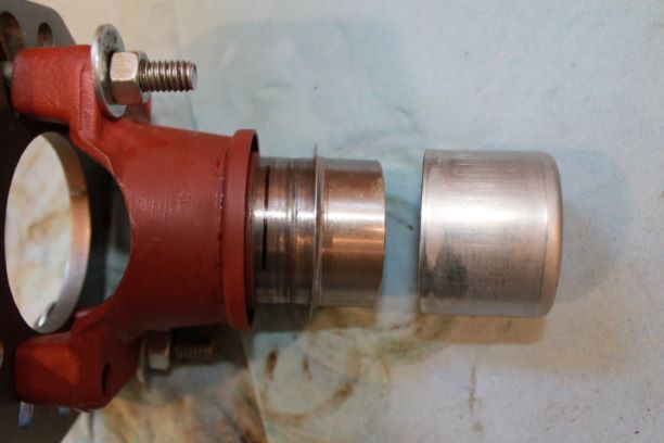
I have a significant groove in the surface upon which the oil seal rides. I have elected to use a speedi sleeve. I am using Shaft-Eze brand of sleeves and the part number is 99156 for shaft diameter 1.559-1.565" I also marked teh seating depth with a Sharpie so I do not over or under seat it. I want it to ride over the grove with enough room for error.
The installation is fairly simple. You can decide if you want to put J-B Weld under the sleeve. I elected not too as the tightness of the slip should prevent any slippage.
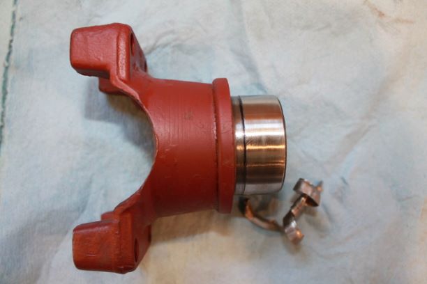
Once the sleeve is driven down to the sharpie line, you can remove the driving lip. There was not much room below the lip and between the flange lip of the yoke, so I took a flat tip screw driver and placed it on the lip. With a sharp downward rap, it separated the lip from the sleeve. With a bit of prying and use of ships I was able to peel the lip off like a spam can. I used some 400 grit sand paper to ensure there were no sharp or jagged edges on the sleeve.
Here is the finished product. The oil seal rides nice and snug.
Finishing the Rear Axle
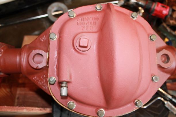
In the wheel section I documented the installation of the wheel hubs and their bearings. I also installed the wheels on the hubs. I secured the rear differential housing on top of its gasket and fastened the 5/16 NC bolts with new lock washers onto the cover. Those were torqued to 15 ft lbs. I also used Permatex Thread Sealer on the bolts. Overkill!
While doing research on parts and procedures I found that later in the war a simple metal axle guide was installed behind the inner axle oil seal. This cone shaped guide allowed one to insert the axle and guide it gently through the seal without snagging the oil barrier on the sharp splines. I ended up opening the diff back up, removed the carrier and seals and installed these cones and new seals, making sure to keep the lip of the rubber seal in toward the differential. It's easy to install them backwards as you can see from my image way above.
Another detail I overlooked was the Oil line Tee fitting bracket. The one installed on my GPW wasa fabricated piece of metal with no markings. I found another original bracket and installed that under the two cover bolts at the 10 and 11 o'clock position as specified.

Finishing the Rear Axle
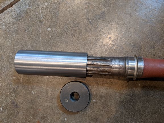
I still have a few more things to do to finish the rear axle. I took the time to install a speedi sleeve on the scalloped axle that had wear on the surface where the oil seal rides. I used a piece of steel pipe that closely matched the outer diameter of the spedi sleeve as does the install tool that comes with it. The problem with the install tool is that it is not long enough to drive the sleeve far enough down onto the axle.
The image shows the pipe. I used a driver and hammer to gently get the sleeve to the right depth over the worn portion. I wish the sleeve was a bit wider, as you have to get this seated over just the right portion of the axle and it leaves little room for adjustment.
I have a small puch out list for the rear axle: install axle gaskets, install axle, paint axle end, install Differential Ratio Tag, Install oil line and oil line bracket, torque down the breather vent, seal fill and drain plugs, fill with 90wt oil.
