GPW 14518 Steering Gear
Disassembly
FROM THE TM:
c. Disassembly.
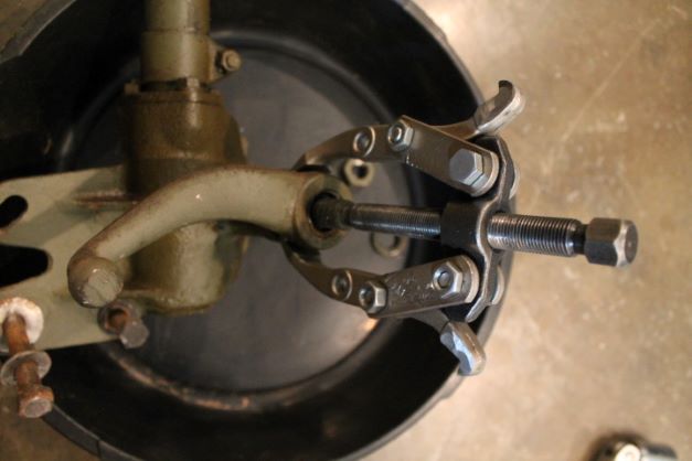
( 1) REMOVE PITMAN ARM. Remove the nut and lock washer that hold the Pitman arm on the sector shaft assembly. Pull the Pitman arm off the steering sector shaft assembly with a standard Pitman arm puller. A simple two jaw puller works fine. As with most pitman arms, mine is worn about 1/3 of the way through the neck below the ball. I will use either a reproduction part or a very nice MB arm that I have..
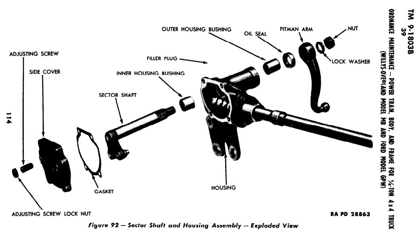
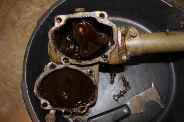
(2) REMOVE STEERING SECTOR SHAFT ASSEMBLY (fig, 92). Remove the four cap screws that hold the side cover to the housing and remove the side cover and gasket. Slide the sector shaft assembly from the housing. Note the locations of the two copper crush washers. My cover screws are unmarked as they were on the other two in the shop.
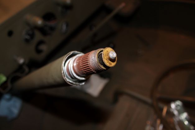
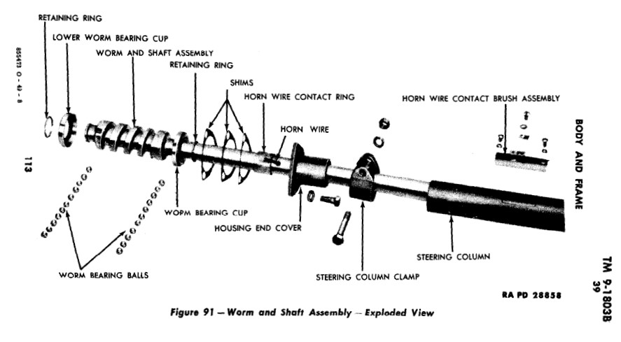
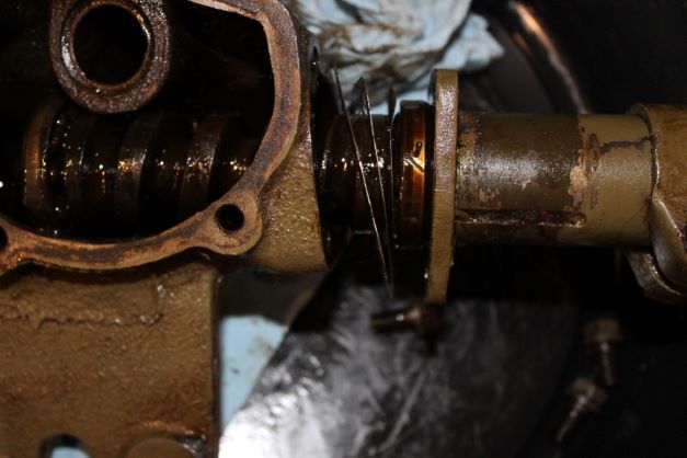
(3) REMOVE STEERING GEAR WORM AND SHAFT ASSEMBLY FROM HOUSING. Remove the three cap screws that secure the housing end cover and shims to the housing. Slide the housing and shims off the worm and shaft assembly. . The steering shaft is supposed to slip right out of the steering tube, but because the upper steering shaft bearing (near the steering wheel) was rusted to the shaft and needed gorilla intervention to remove. The TM image of the bearing is whown below. The parts manual lists it as:
Bearing GPW 3517
(4) REMOVE STEERING GEAR WORM BEARINGS . Remove the retainer ring that secures the steering gear worm lower bearing cup at the end of the shaft assembly. Remove the bearing cup and balls. Remove the retainer ring that secures the worm upper bearing cup to the shaft assembly. Slide the worm bearing cup up on the shaft and remove the balls.

Inspection and Cleaning
d. Cleaning, Inspection, and Repair.
( 1) CLEANING AND INSPECTION Clean all parts thoroughly in dry-cleaning solvent Replace a housing assembly or side cover that is cracked or damaged. Replace the expansion plug in the lower end of the housing if it is loose.
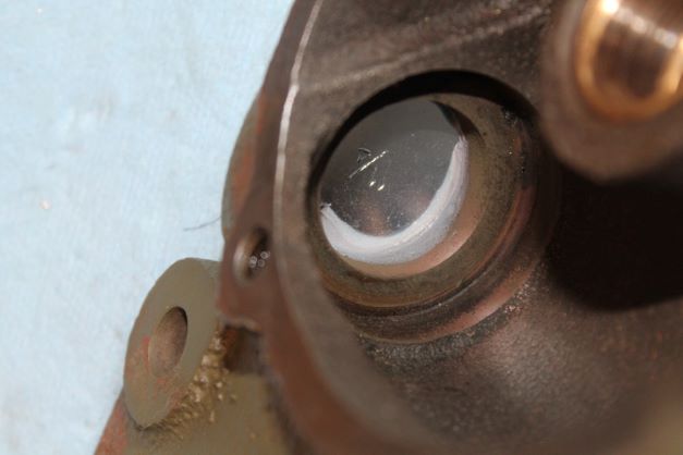
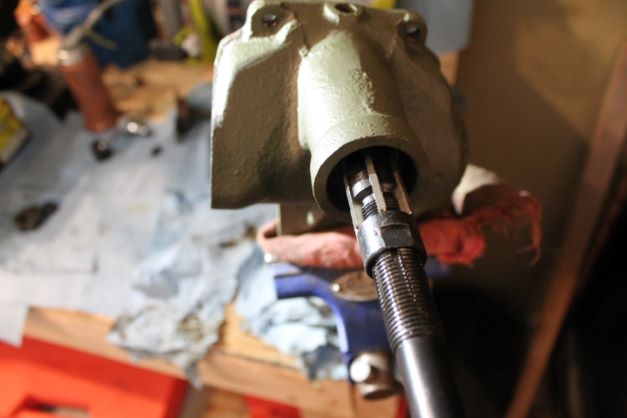
I have a new expansion plug in my kit so that will get replaced. I put some RTV in the recess for the expansion plug for insurance against leakage. I installed the expansion cup using a thin wall 7/8 socket that fit just inside the inner diameter of the expansion plug recess. I used that to drive it home with no problem.
Replace the inner and outer bushings in the housing if worn larger than 0.876 inch inside diameter. Replace a sector shaft assembly that has flat spots on the tapered studs or that has chipped studs. Replace the sector shaft if the shaft measures less than 0.870 inch at the bearing surfaces. Replace the worm and shaft assembly if the worm is excessively worn, ridged, scored, or chipped.
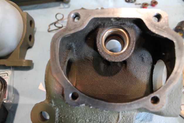
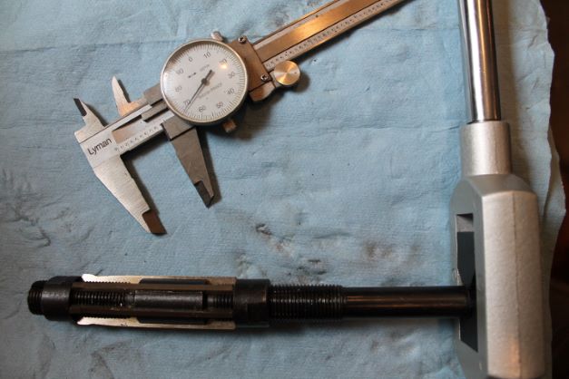
The sector shaft studs have two flat spots on them so I am replacing it with another that is unworn. The shaft on the replacement one measures 0.8755". I am replacing the two bushings as well and will ream them IAW the instructions below. I have a set of expandable reamers and will ream to 0.001" above the shaft, or 0.8765. I think the recommended difference is actually 0.0015" clearance.
Replace a worn, pitted, or cracked worm upper and lower bearing cup. Replace a broken or damaged horn wire. Replace a steering column tube that is bent or damaged. Replace the whole assembly if it is damaged Replace any balls with flat spots. Replace the steering column tube bearing if worn.
Here are the instructions for replacing the two bushings:
Housing, Inner, and Outer, Bushing Replacement. Remove the housing oil seal with a small punch or chisel. Drive a small punch or chisel between the housing and the joint in the bushings, until the ends of the bushings overlap. Tap the bushings out of the housing. To install the bushings, press the outer bushing into the housing until it is flush with the oil seal shoulder in the housing assembly. Press the inner bushing into the housing. Ream the bushings to 0.875 inch diameter with reamer
41-R-1220.
I have a full set of expensive expandable reamers. They are really useful for this type of job. First install the bushings and then expand the reamer so that it just fits into the bushing with a micro-gap. Make sure the sector shaft will not fit either just to be safe. You are trying to "sneak up" on the correct diameter of the bushings. If you make a mistake and expand the reamer too much, you will overshoot your target of 0.001". I only turn the nut on the tool 1/2 revolution each time to make an incremental expansion, then measured twice with the calibers. The reamer gets larger as it moves up the shaft, so measure the widest part.
Take small bites, and be patient. The sector shaft will not slip in, and then all of a sudden it slides right in with no side to side play. Just take your time. It took me 7 adjustments of the nut to reach nirvana.
Gear Box Assembly
e. Assembly.
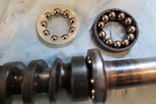
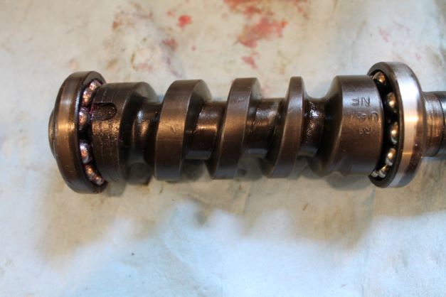
(1) ASSEMBLE WORM AND SHAFT ASSEMBLY. Place the 11 worm bearing balls in the upper worm bearing cup. Slide the cup and retainer ring in place. Place the balls in the lower worm bearing cup and install the cup and retainer ring on the lower end of the shaft.
The reproductions steering gear box kits are questionable at best. I checked the cup and bearing s from the original set up and elected to use those. I am not a fan of plastic bearing retainer cage.
Installing the lower ball bearings requires the cup to be slipped over the shaft at a slight angle and then you can feed the 11 balls into the cup via the machined grove. Once the last one is in and the cup is pulled up toward the worm gear, it keeps everything together for installation as long as you don't twist the cup at an angle.
The upper worm gear cup is easy to fill. Once the 11 balls are installed, slide it up towards the collar and slide the lock ring into the grove.
(2) INSTALL WORM AND SHAFT IN HOUSING. Slide the worm and shaft assembly in the housing. Install shims approximately 0.024 inch thick and the housing end cover on the shaft. Install the three cap screws that secure the housing end cover. Turn the shaft by hand, if it is too tight, shims must be added, if too loose shims must be removed. The correct adjustment is when shaft turns freely but has no end play. Shims are supplied in 0.0035, 0.0025and 0.0065 inch thicknesses.
I cleaned up the worm gear and elected to prime the shaft to prevent rust. The tube and the inside of the worm gear were so full of crud. I used a 20 gauge bore brush to scrub the crap out of the worm gear tube. It took several passes to get it relatively clean. The worm gear is in really nice shape with little wear and no chips. With the worm gear in the box with the two bearings installed, you can slip the required shims onto the shaft and then the shims, collar and 3 bolts. The original shim stack was 0.035". I installed the same amount and ended up with good rotation on the shaft and no up and down movement.
(3) INSTALL SECTOR SHAFT ASSEMBLY (fig. 92). Slide the sector shaft assembly into the housing, making sure the two tapered studs engage in the worm.
(4) INSTALL SIDE COVER ON HOUSING. Install a new side cover gasket and cover on the housing. Install the side adjusting screw and lock nut in the side cover. Turn the shaft counter-clockwise until the shaft cannot be turned any farther. Turn the shaft clockwise until it cannot be turned any farther, counting the complete and part revolutions of the shaft and then turn the shaft counterclockwise half the number of turns. This will center the shaft. Turn the side adjusting screw in, until a slight drag on the
shaft can be felt at this point. Tighten the adjusting screw lock nut and recheck the adjustment.
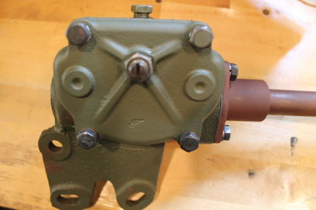
I installed the clover, the fill plug and the adjustment nut and bolt just to check the fitment. The early GPW used two copper crush washers on the lower bolts and two lock washers on the upper. Many restorers are using thread sealant on the lower bolts as they penetrate into the steering box. The upper two bolts do not.
(5) INSTALL STEERING COLUMN TUBE ON SHAFT. Install the steering column clamp on the steering column with the bolt side of the clamp in line with the horn wire contact brush opening in the steering column. Slide the steering column tube down onto the housing end cover, making sure the horn wire contact brush opening in the steering column is in a vertical position when the housing base is in normal position. Tighten the clamp bolt.
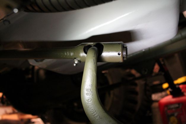
(6) INSTALL PITMAN ARM. Place the Pitman arm on the sector shaft assembly, making sure the line on the Pitman arm is in line with the mark on the sector shaft assembly and that the ball joint on the Pitman arm is facing downward when the shaft is centered. Install the lock washer and nut that secure the Pitman arm to the sector shaft.
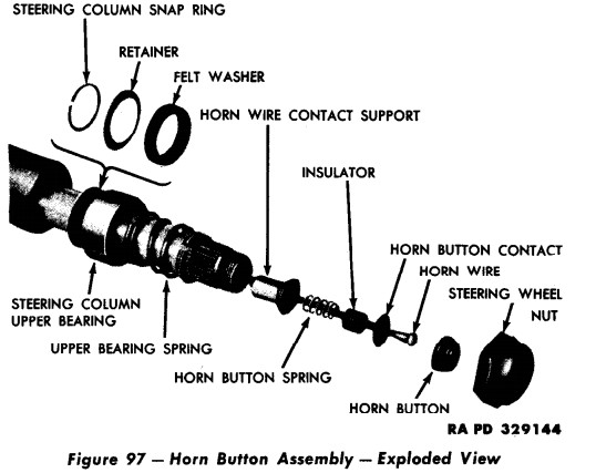
(7) INSTALL HORN WIRE CONTACT BRUSH ASSEMBLY. Hold the horn wire contact brush assembly in place on the steering column and install the two hold-down screws.
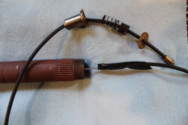
The worn wire kit that I had only included the horn wire with the copper button soldered on top. I salvaged the lower cup, the spring, the bakelite plug and the contact washer. They are all installed as shown in the TM parts illustration.
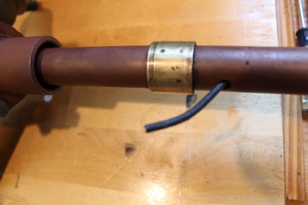
I slipped a piece of safety wire through the hole near the brass collar and up the tube. I attached it to the wire with a piece of electrical tape. Use enough because when you make the pull through the hole, the friction on the wire and tape may pull the wire and tape off of the wire.
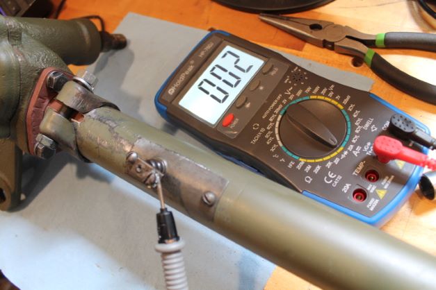
I soldered the wire to the collar making sure I left enough slack for the button to stick up a bit and be able to be compressed on the spring to make contact. If you leave too much wire, it wont push down, too little and you pull the contact down and your horn will constantly sound. Here is the dry fit prior to final painting and continuity check.
I installed the tube cover, the clamp and bolt onto the collar and dry fit everything by loosely mounting it onto the frame using the three frame bolts.
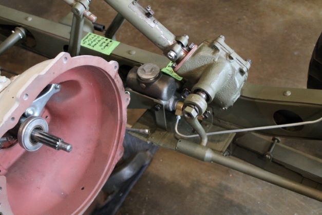
Final Steering Assembly
Before I began the final assembly I checked to see if the steering column without the tube would fit into the firewall opening with the body mounted on the tub. Everything worked well with the following considerations:
- Make sure your front wheels are straight ahead.
- Remove the tube, the bell crank, and the tube clamp and the tube clamp screw and hardware.
- Verify that you have the steering shaft set to neutral. (Centered) Turn steering all the way to one side. Then turn the steering wheel completely to the other way. Note the number of turns. Then turn the steering wheel shaft 1/2 the number of turns. In my case that was 1 3/4 turns. Make a mark on the shaft and end so you can line it back up.
- Insert the steering shaft through the hole in the firewall
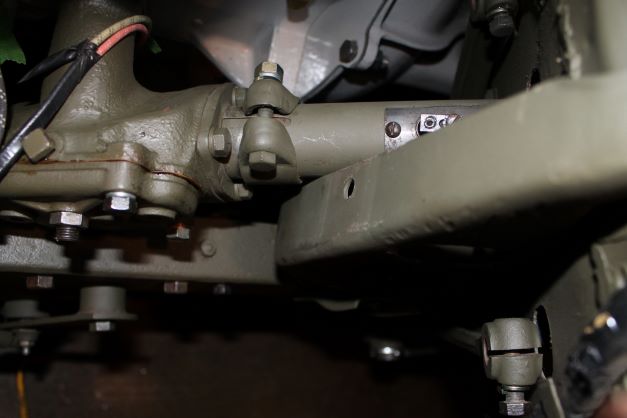
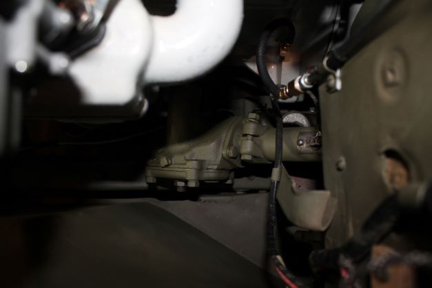
- Secure the steering gear box with the three long bolts, the lock washers and nuts. Finger tight is fine.
- Insert the rubber boot and metal dust shield onto the pittman arm.
- Install the cups and springs into the rear of the drag link. The front should already be installed onto the bell crank and the screw tighened finger tight.
- Insert the ball of the pittman arm into the rear opening of the drag link with the ball between the two ball seats. Tighten the ball plug finger tight so that the ball remains in the link.
- Insert the pittman arm onto the splines of the sector shaft. You may need to rotate the shaft slightly to get the splines to line up. (Small amount here)
- Install the sector shaft lock washer and nut finger tight.
- Insert the tube clamp down the shaft, throgh the hole in the firewall and onto the gear box housing end. INsert the long bolt, lock washer and nut finger tight.
- Slide the steering column tube over the steering shaft, keeping the horn wiring contact in the upright position.
- Slide the tube into the clamp and over the gearbox housing end with the clamp holding everythign in place.
- install the steering wheel bearing, spring, wheel, horn button and nut in proper order. (Orient the wheel so that the 3 spokes form a "Y".
- Tighten ALL hardware, bolts, nuts, end plugs etc.
- Lube the drag link
- Fill the gear box with 130wt oil.
