BEFORE
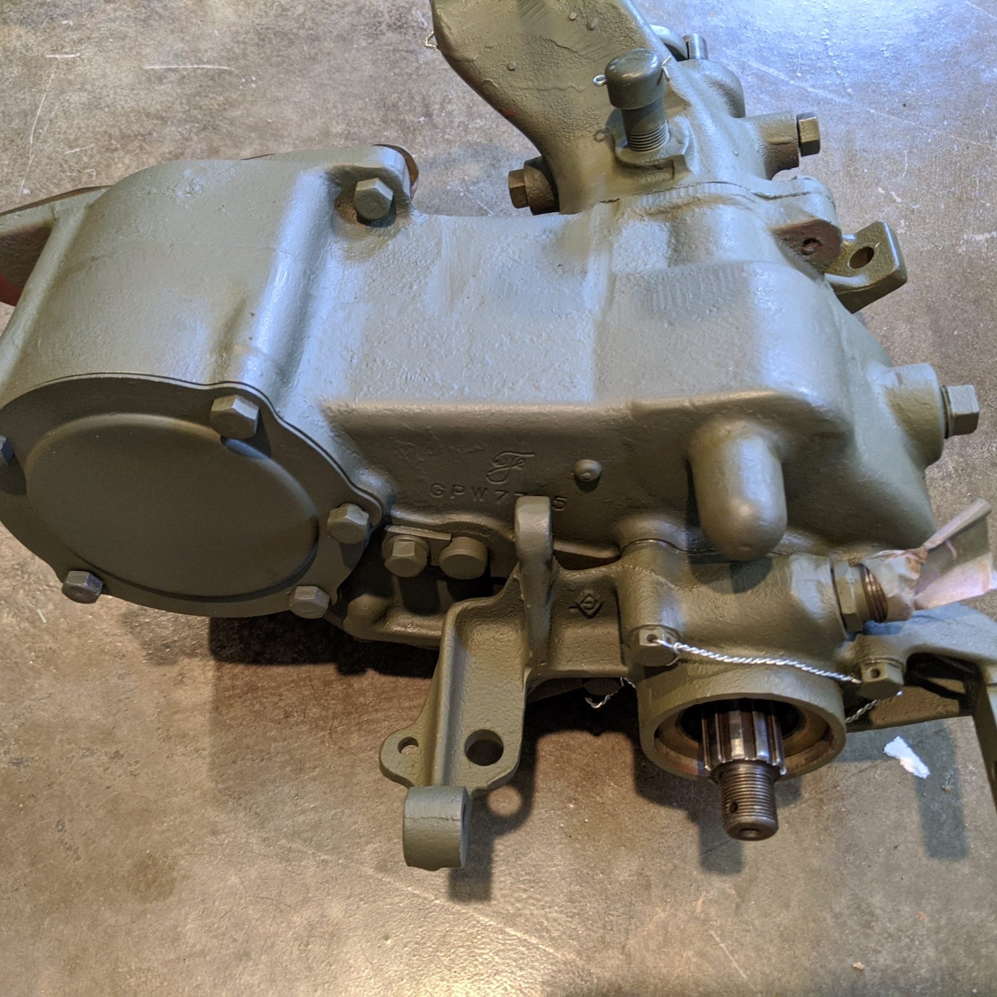
AFTER
Tear Down Procedures from TM 9-1803B
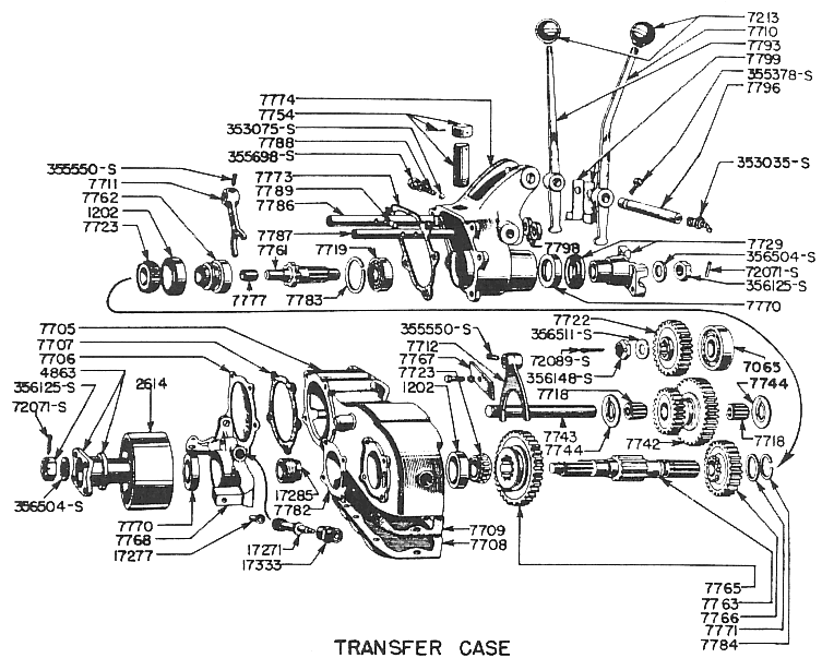
For the Follow-on discussions of the transfer case rebuild, I'll generally refer to the parts diagram above taken from the parts Manual. Below are the disassembly instructions from the TM
TM 9-1803B RA PD 21657
12. DISASSEMBLY.
a. Remove Brake Band and Drum Assembly (fig. 28). Remove the two anchor screws from the brake band. Remove the brake band
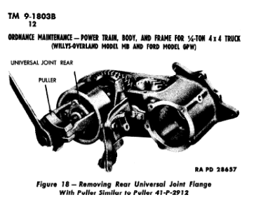
adjusting nut and adjusting screw. Remove the clevis pin from the hand brake linkage. Remove the brake band assembly. Remove the castellated nut that secures the universal joint flange to the output shaft. Install puller 41-P-2912 on the universal joint flange and remove the flange and brake drum (fig. 18).
b. Remove Rear Output Shaft Bearing Cap (fig.26) Remove the four cap screws that secure the rear output shaft bearing cap to
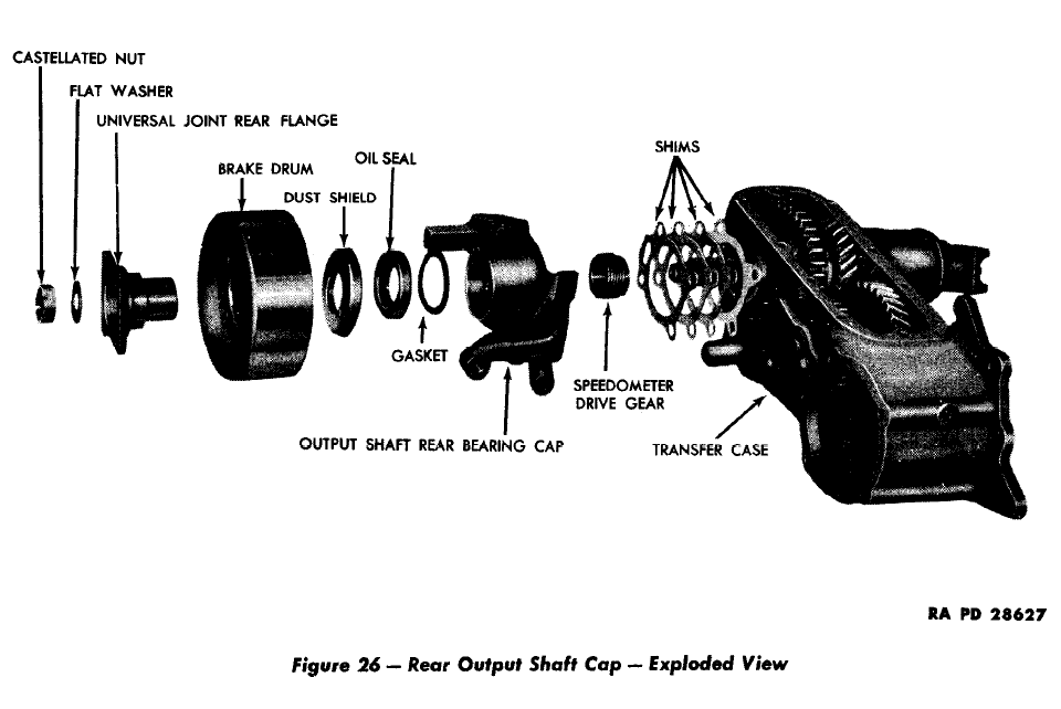
transfer case housing. Remove the rear output shaft bearing cap. Remove the rear bearing cap shims, Remove the speedometer drive gear from the output shaft.
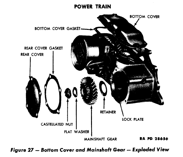
c. Remove Intermadiate Gear and Bottom Cover (figs. 25 and 27). Remove the 10 cap screws that secure the bottom cover to the
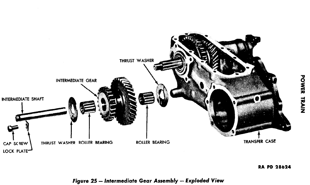
transfer case and remove the bottom cover. Remove the cap screw that secures the lock plate. Remove the lock plate. With a suitable driver, remove the intermediate gear shaft. Remove the intermediate gear, thrust washers, and roller bearings through the bottom of the transfer case.
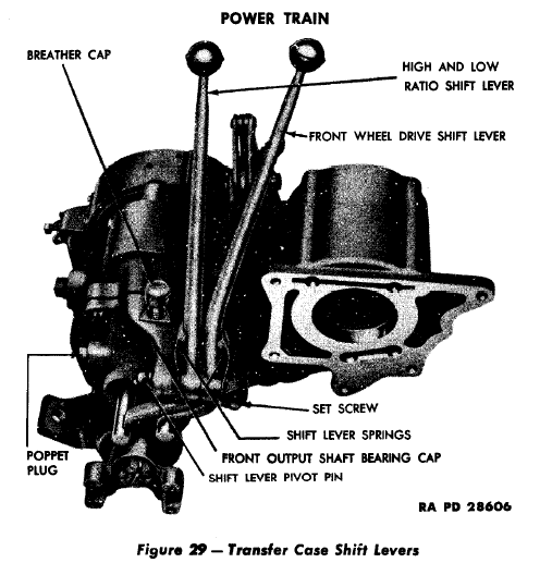
d. Remove Shifter Shaft and Front Output Shaft Bearing (fig. 29). Shift front axle drive to the engaged position. Remove the
poppet plug, spring, and ball on both sides of the output shaft bearing cap. Remove the five cap screws that secure the front output shaft bearing cap to the transfer case. Remove the front output shaft bearing cap as an assembly with the universal joint flange, clutch shaft, bearing, clutch gear, shifter fork, and shifter rod. Be careful not to lose the interlock in the front bearing cap.
e. Remove Output Shaft (fig. 19). Insert a screwdriver between the snap ring and output shaft bearing and pry the output shaft bearing away from the snap ring. Remove the snap ring from the groove in the output shaft. Pull the output shaft out from the rear of the housing. The output shaft bearing, snap ring thrust washer, output shaft sliding gear, and output shaft gear can now be removed through the bottom of the transfer case.
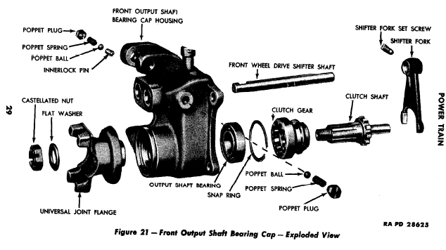
f. Disassemble Front Output Shaft Bearing Cap (fig. 21). Remove the set screw that secures the shifter fork to the front wheel drive shaft. Slide the shifter fork out of the shifter fork. Remove the shifter fork and clutch gear from the bearing cap. Remove the snap ring that secures the output shaft bearing and remove the output shaft bearing from the bearing cup.

Step A: Remove Brake Band Assembly
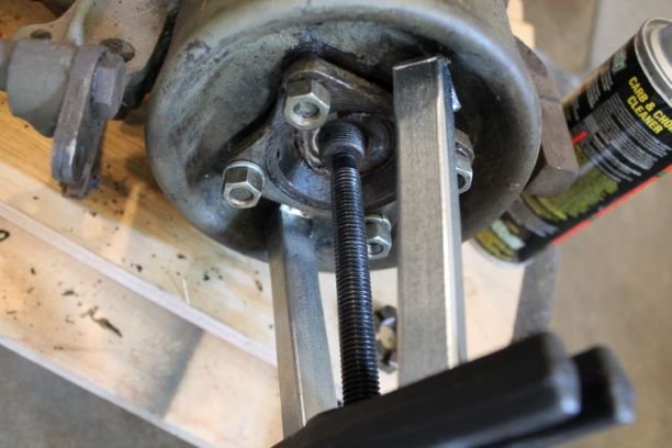
a. Remove Brake Band and Drum Assembly (fig. 28). Remove the two anchor screws from the brake band. Remove the brake band
adjusting nut and adjusting screw. Remove the clevis pin from the hand brake linkage. Remove the brake band assembly. Remove the castellated nut that secures the universal joint flange to the output shaft. Install puller 41-P-2912 on the universal joint flange and remove the flange and brake drum (fig. 18).
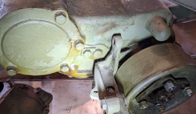
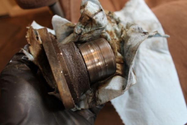
It was hard to get the puller feet under the flange on both sides. It eventually worked this way. The oil slinger/dirt shield (part not listed in TM) that is between the drum and the oil seal was on very tight. Note the heavy use of silicone to seal the splines. The flange shaft is HEAVILY grooved from dirt. I'll replace this as I don't want to use a speedy sleeve.
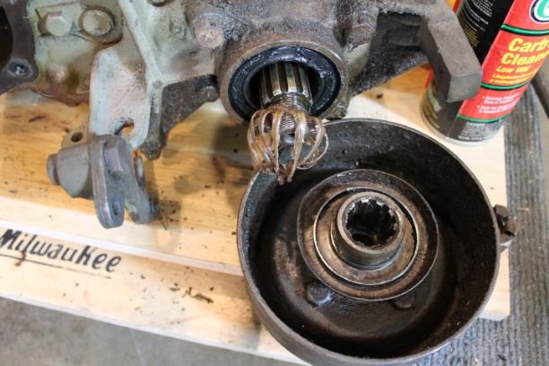
Step B: Remove Rear Output Shaft Bearing Cap
b. Remove Rear Output Shaft Bearing Cap (fig.26) Remove the four cap screws that secure the rear output shaft bearing cap to
transfer case housing. Remove the rear output shaft bearing cap. Remove the rear bearing cap shims, Remove the speedometer drive gear from the output shaft.
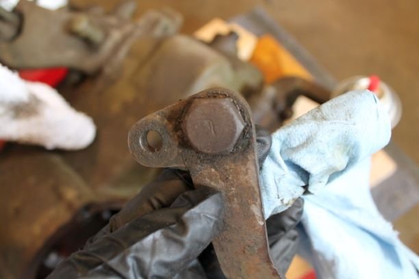
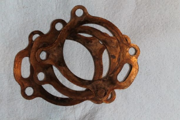
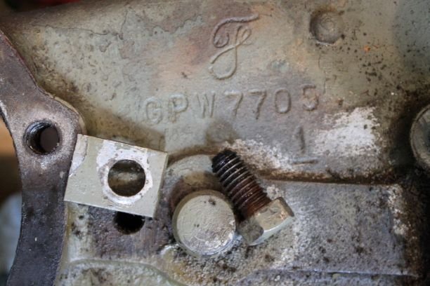
OZ: I had one more hand brake part that needed to be removed, so I took the hand brake cam off. It has a nice F marked bolt. off. This GPW came with no other HB parts. Four Bearing cap bolts came off very nicely revealing three shims. A very simple step this was.
7782-A 1ea 0.003"
7782-C 2ea 0.031"
Step C: Remove Intermediate Gear and Bottom Cover
c. Remove Intermediate Gear and Bottom Cover (figs. 25 and 27). Remove the 10 cap screws that secure the bottom cover to the
transfer case and remove the bottom cover. Remove the cap screw that secures the lock plate. Remove the lock plate. With a suitable driver, remove the intermediate gear shaft. Remove the intermediate gear, thrust washers, and roller bearings through the bottom of the transfer case.
OZ:
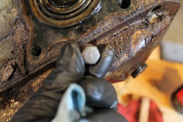
The bottom cover 7708 came off nicely. It was pleasing to see 10 Ford marked screws 20326-S7 5/16-18 x 5/8" hex head bolts and associated washers 34806-S2.
I removed the shaft lock. It looks like this is not an original part, but The bolt is F Marked also. The shaft was easy to remove with a brass drift, driving front to rear.
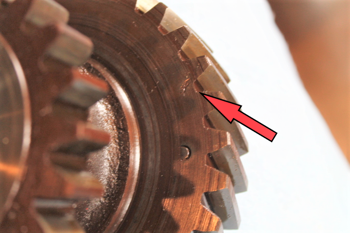
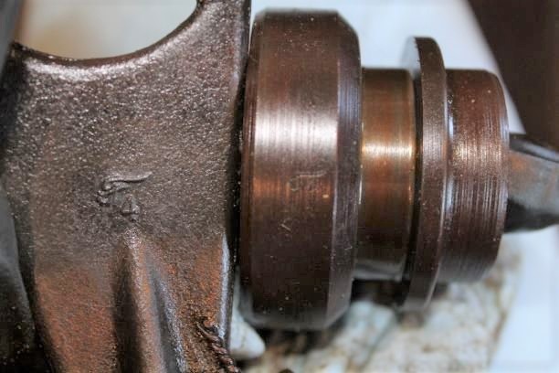
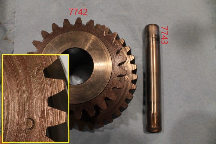
I removed the gear and found a nice f-script on the gear inside face. It looks reusable, but I have to mic the inside and length to see.
Step D: Remove Shifter Shaft and Front Output Bearing Shaft
d. Remove Shifter Shaft and Front Output Shaft Bearing (fig. 29). Shift front axle drive to the engaged position. Remove the poppet plug, spring, and ball on both sides of the output shaft bearing cap. Remove the five cap screws that secure the front output shaft bearing cap to the transfer case. Remove the front output shaft bearing cap as an assembly with the universal joint flange, clutch shaft, bearing, clutch gear, shifter fork, and shifter rod. Be careful not to lose the interlock in the front bearing cap.
OZ:
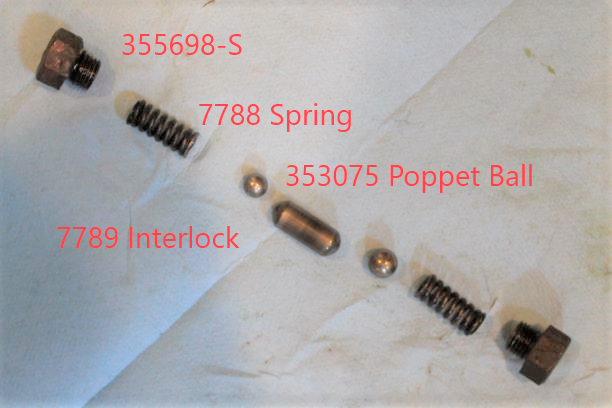
The left shifter (Front Axle Drive), when viwed from the driver's position, should be put in the aft position as shown in TM 9-803. The poppet springs come out with a pick, and tilting the transfer case side to side will allow the balls to roll out. THe interlock is gooed in, so I pushed it out after dissasembly.
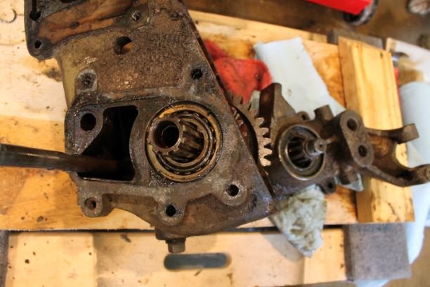
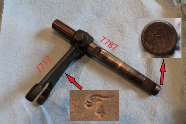
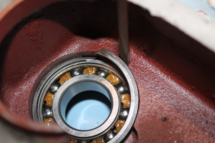
I had already loosened the shaft nut and removed the flange. it is heavily grooved like the rear flange so it will need to be replaced. The five bearing cap hex nut screws come out fairly easily. They were not F marked, but tapped for safety wire with two holes. The two pieces needed a bit of coaxing to remove, and the front axle shifter shaft 7787 did not want to come all the way out. it hung up a bit in the cap and I had to use a drift to "coax" it out. I suspect the end was damaged and would not pass through the inner recess. Not a big problem.
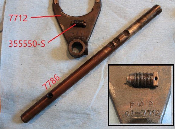
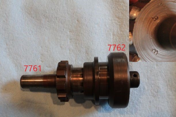
The fork 7711 and the Transfer Case Gear Clutch 7762 are also nicely F marked.
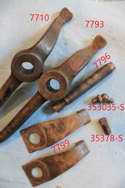
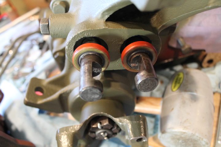
I took the opportunity to remove the breather vent shaft, cover 7754 and the shifters 7710, 7793, and the lever springs 7799
Step E: Remove Output Shaft
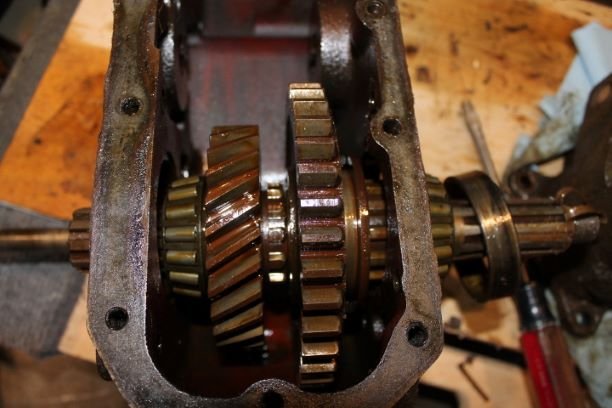
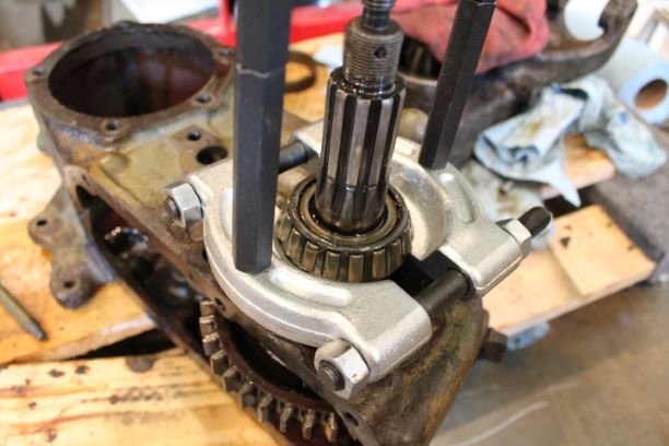
e. Remove Output Shaft (fig. 19). Insert a screwdriver between the snap ring and output shaft bearing and pry the output shaft bearing away from the snap ring. Remove the snap ring from the groove in the output shaft. Pull the output shaft out from the rear of the housing. The output shaft bearing, snap ring thrust washer, output shaft sliding gear, and output shaft gear can now be removed through the bottom of the transfer case.
OZ:
I could not move the rear bearing out of the way to get at the snap ring. I used a block of wood to gently drive the shaft forward. This allowed me to see "what was going on in there" Once I had some room I was able to see what the TM was referencing. Figure 19 actually shows it well. I was cursing the Snap Ring so much I did not take a picture. It took a prybar to move the bearing aft so I could actually get two screwdrivers in there to move it over the shaft. Its not too stiff, just difficult to get a hold of. Two screwdrivers and snap ring pliers did the job, and don't forget to hold your tongue in the right place on the inside of your mouth. If you use a lot of foul language it helps you to feel better!

Step F: Disassemble Front Output Shaft Bearing Cap
f. Disassemble Front Output Shaft Bearing Cap (fig. 21). Remove the set screw that secures the shifter fork to the front wheel drive shaft. Slide the shifter fork out of the shifter fork. Remove the shifter fork and clutch gear from the bearing cap. Remove the snap ring that secures the output shaft bearing and remove the output shaft bearing from the bearing cup.
I failed to get any images of this stage. As I was removing the front seal, I cracked the lip that holds it in. This rendered the cap unuseable. I sourced another take-off part as a replacement. Lesson learned: use a seal puller, dont drive them out from the back as you can "catch" the inner lip and crack it. It's not too thick.
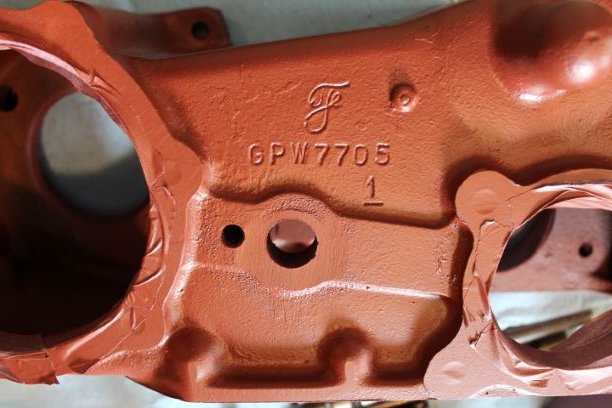
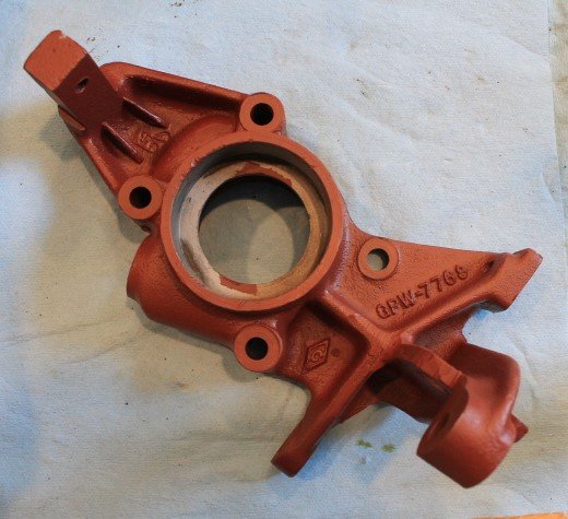
I took the opportunity to thoroughly clean the two caps and the transfer case. I blasted them, washed them, and baked out the remaining oil and water on my outdoor grill at 250 degrees for about 30 minutes, When doing this you will get flash rust, so steel wool followed by priming was my solution. I masked all of the machined surfaces and the shaft and bearing surfaces before painting.
For setting the shims and blocking space on the T-84 Transmission, it is highly advisable to use the transfer case and output gear rather than clamps to set the s"slop" in the blocking rings. (See Transmission Section for those instructions)
Cleaning Inspection and Repair
13. CLEANING, INSPECTION, AND REPAIR.
a. Cleaning. Clean all parts thoroughly in dry-cleaning solvent. Clean the bearings by rotating while immersed in dry-cleaning solvent until all trace of lubricant has been removed. Oil the bearings immediately to prevent corrosion of highly polished surfaces.
b. Inspection.
(1) Transfer Case Assembly (Fig. 27) Inspect the transfer case housing for cracks or damage of any kind. Inspect the bottom and rear cover for bent or damaged condition. Replace the gaskets on the bottom and rear covers.
(2) Front Output Shaft Bearing Assembly (fig 21)
(a) Front Output Shaft Bearing Cap Housing (fig. 20). Replace the front bearing cap if it is cracked or damaged. Shifter shaft and output shaft oil seals must be replaced. (subpara. c. below)
(b) Front Wheel Drive Shifter Shaft and Fork (fig. 21) Replace the Front Wheel drive shifter shaft if bent or damaged. Replace the fork if it has stripped set screw threads, if it is cracked or has bent forks.
(c)Crutch Shaft and Gear (fig. 21)Replace the clutch shaft if the splines or gear teeth are chipped or worn, if the gear has any teeth missing. Check the diameter of the pilot end of the shaft. If the diameter is less than 0.625" replace the clutch shaft. Replace if the clutch gear if it is worn or has any broken teeth.
(d) Output Shaft Bearing (fig. 21) Ball bearings with loose or discolored balls or with pitted or cracked races must be replaced.
(3) INTERMEDIATE GEAR ASSEMBLY (fig. 25). ‘Replace the intermediate gear if excessively worn, or if any teeth are damaged Check
the thickness of the thrust washers. If the thrust washers are less than 0.093" in thickness, replace them. Check the diameter of the intermediate gear shaft If the diameter is less than 0.750", replace the intermediate gear shaft. Replace the roller bearing, if the rollers are scored or have flat spots.
(4) REAR OUTPUT SHAFT BEARING (Fig. 26) Replace the output shaft bearing cap if cracked or damaged. Replace the speedometer drive gear if it is worn or has damaged teeth. Replace the oil seal in the output shaft bearing cap housing (subpar. c, below). Replace the brake drum if it is worn or bent Replace the universal joint rear flange; if the splines are worn, Replace the dust shield on the flange if bent.
(5) OUTPUT SHAFT ASSEMBLY (fig. 24). Replace the output shaft if the splines are worn. Small nicks can be removed by honing
and then polishing with a fine stone, Measure the inside diameter of the bushing in the output shaft. If it is greater than 0.627", replace the output shaft Replace the output shaft gear if it is worn or has any damaged teeth. Replace the sliding gear, if it is worn or has damaged teeth. Measure the thickness of the thrust washer. If the thrust washer thickness is less than 0.103", replace it. Replace the roller bearings if they are scored or have flat spots, or if the races are nicked or cracked.
(6) UNDER DRIVE SHIFTER FORK ASSEMBLY (fig. 24). Check the fork for stripped set screw threads, cracked or bent forks. Replace if in any of these conditions. Replace the under drive shifter shaft if it is bent.
(7) SHIFT LEVER ASSEMBLY (fig. 29). Replace the shift levers if found bent or damaged. Replace the shift lever spring if bent or cracked. Measure the diameter of the shift lever pivot pin. If the diameter is less than 0.500", replace the pivot pin.
c. Output Shaft Bearing Cap Oil Seal Replacement (fig. 20). Drive the old oil seal out of the output shaft bearing cap housing, using
a suitable driver. Drive the oil seals out, working from the inside of the cap housing. To install a new oil seal, use a driver the size of the oil seal and drive the new seal in the output shaft bearing cap housing.
Assembly
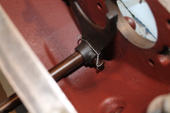
a. Assemble the Front Output Shaft Bearing Cap. Insert the bearing in the output shaft bearing cap. Install the snap ring that secures the bearing in the output shaft bearing cap. Insert the clutch shaft through the bearing from the inside of the output shaft bearing cap. Insert the front wheel drive shifter shaft in the output shaft bearing cap through the outer side of the output shaft bearing cap. Place the front wheel drive shifter fork in position on the clutch gear. Slide the shifter fork on the shifter shaft and clutch gear on the clutch shaft together. Install the set screw in the shift fork and secure with a lock wire. Install the universal joint flange on the clutch shaft. Install the washer and castellated nut that secure the universal joint flange to the clutch shaft.
b. Install Under Drive Shifter Fork. Place the under drive shifter fork in the transfer case housing. Insert the under drive shifter shaft in the transfer case and shifter fork. Install the shifter fork set screw that secures the fork to the shifter shaft. Secure the set screw with lock wire.
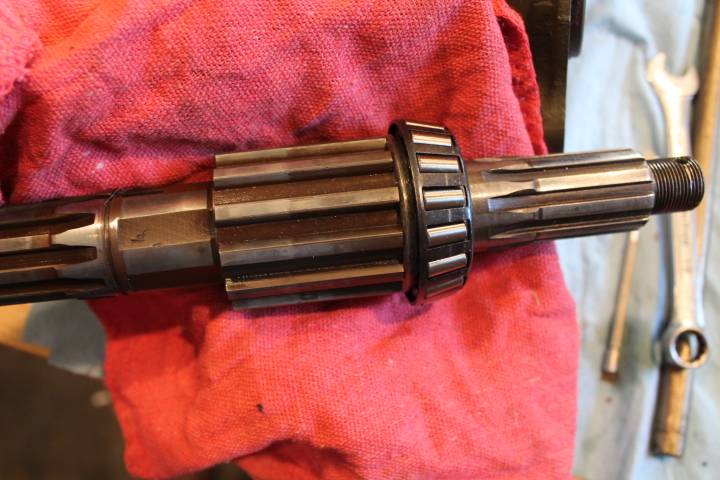
c. Install Output Shaft in Transfer Case. Press the rear output shaft bearing on the output shaft. Set the output shaft sliding gear in the transfer case with the shifter fork in the channel of the sliding gear. Place the output shaft gear in the transfer case with the shoulder of the output shaft gear facing the sliding gear. Insert the output shaft in the transfer case and through the gears. Slide the thrust washer on the output shaft. Install the snap ring that secures the output shaft gear on the shaft Slide the front output shaft roller bearing on the output shaft and, using a suitable driver, tap the roller bearing snug against the snap ring. Tap the front roller bearing cup in the transfer case until the cup is slightly below flush with the transfer case. Tap the rear bearing cup in the transfer case until the cup is approximately l inch from the transfer case surface.
d. Install Front Output Shaft Bearing Cap to Transfer Case. Place a new gasket in position on the transfer case. Install the interlock in the interlock opening on the bearing cap. Slide the front output shaft bearing cap on the under drive shifter
shaft, being careful not to damage the oil seal in the output shaft bearing cap. Install the five bolts that secure the front bearing cap to the transfer case. Install the poppet ball, poppet spring and poppet plug on both sides of the front bearing cap .
e. Install Intermediate Gear. Insert the roller bearings
in the intermediate gear. Place the thrust washers in the transfer case, with the side having the bronze facing, toward the intermediate gear. Apply grease to the thrust washers to hold them in position, if necessary. Place the intermediate gear between the thrust washers in the transfer case. Install the intermediate gear shaft in the transfer case. Install the lock plate that secures the intermediate gear shaft to the transfer case.
f. Install Rear Output Shaft Cap to Transfer Case. Slide the speedometer drive gear on the output shaft. Install the oil seal in the rear output shaft cap. Install the rear output shaft cap, shims and gasket on the transfer case. Tighten the four cap screws evenly to prevent cracking the output shaft cap. Shims are to be added or removed until the output shaft has no end play, but turns freely. When adjusting the bearings, each time shims are added, the shaft must be free before attempting to tighten the output shaft cap again. Insert the rear universal joint flange in the brake drum. Place the four cap screws in the brake drum and universal joint flange, using a suitable driver, drive the dust shield on the universal joint flange. Install the rear universal joint flange on the output shaft, and install the flat washer and nut.
g. Install Bottom Cover to Transfer Case. Install a new gasket in position on the transfer case. Place the bottom cover on the transfer case. Install the cap screws that secure the bottom cover to the transfer case.
h. Install Brake Band to Transfer Case. Place the brake band on the brake drum. Place the brake band springs between the rear output shaft bearing cap and the ends of the brake band Install the nut and bolt that secure the hand brake linkage to the rear output shaft bearing cap. Insert the adjusting screw through the brake band linkage, brake band springs, and install the adjusting nut. Install the two anchor screws on the brake band.
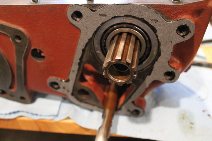
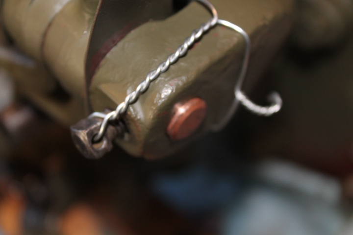
Connecting Bell Housing, Transmission and Transfer Case
From the TM:
15. INSTALLATION.
a. Raise Transfer Case. Raise the transfer case and line up the clutch shaft ball joint in the transfer case. Line up the transfer case with the transmission. Be sure the interlock is in position on the rear of the transmission case before installing the transfer case to the transmission. Install the five cap screws that secure the transfer case to the transmission. Install the mounting bolt that secures the transfer case to the transmission support crossmember.
b. Install Mainshaft Gear. Insert the retainer and mainshaft gear on the transmission mainshaft. Install the flat washer and castellated nut that secure the mainshaft gear on the transmission mainshaft. Place a new gasket and the rear cover on the transfer case and install the cap screws that secure the cover to the case.
There are a few different methods of connecting all of these components. Since I have a clean frame with no body in the way, I am electing to set the bellhousing on the ground, connect the transmission to the bellhousing and then connect the transfer case to the transmission. Here are some torque setting I gleaned from the G503
25-35ft/lbs: Transfer Case to Transmission bolt torque
50-60ft/lbs: Transmission to Bell Housing bolt torque
80-100ft/lbs: Castellated nut holding mainshaft gear to transmission mainshaft torque
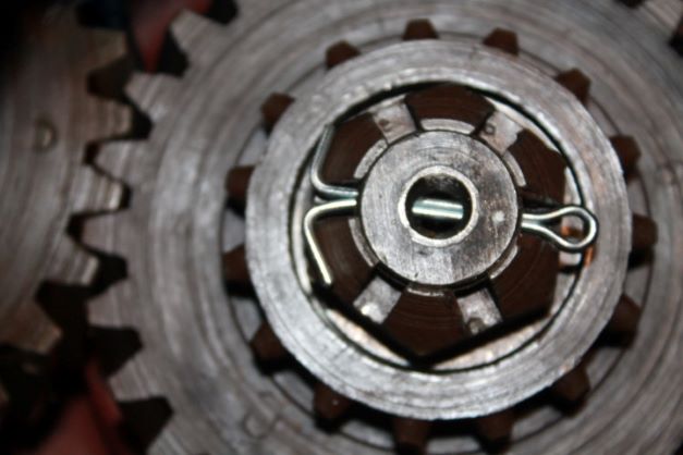
Don't forget to install the oil slinger (retainer) on first, then the mainshaft gear followed by the heavy washer and then the nut.
From what I read, its important to get the torque to at least 80ft/lbs and then check if the hole in the shaft lines up with a groove in the nut. If it does not you should NOT back off the nut, rather you should tighten to get them to allign.
To make it easier to see, I dimpled the shaft at a point where the hole was and marked it with chalk. I tightened to 80ft/lbs and then checked. I was half way between the two grooves, but tightening it put me just short of the hole.
I took some 220grit sandpaper and using a figure 8 pattern eased the bottom of the nut to make it thinner. It took about 2 minutes of sanding to get to the right level. I am at just under 100ft/lbs and it lines up nicely..
Just to make sure, I engages all the gears to make sure they shifted properly. All is fine.
After I touch up the GRAY and OD and install the rear cover, I will use my engine hoist to get this installed on the transmission mount.
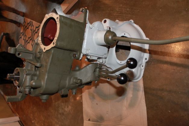
Installing Bell Housing, Transmission and Transfer Case
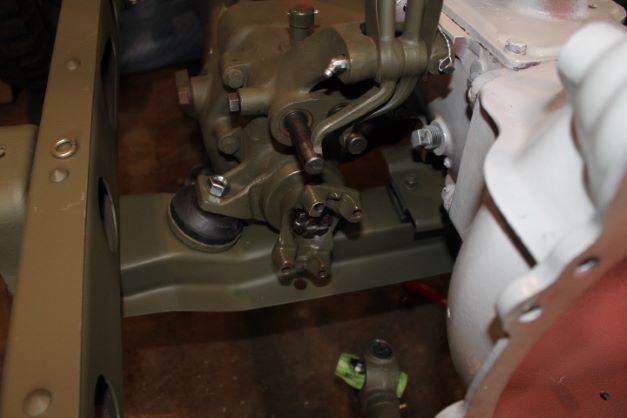
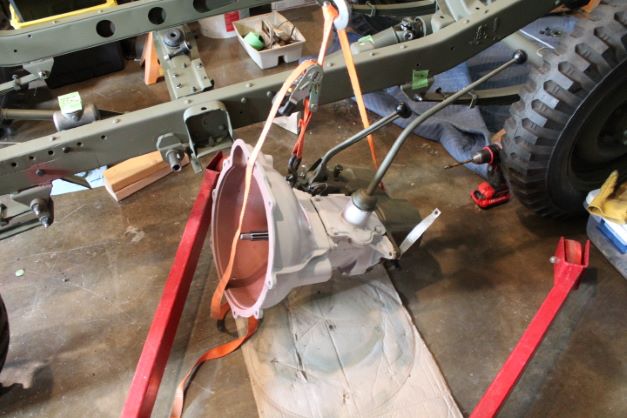
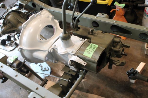
I used my engine hoist to install the bell Housing, Transmission and Transfer Case pack onto the mounting plate. I laid the pack down and found two good hook points that would balance the load and make it fairly level. I used the opening to the bell housing and the eye for the J hook on the rear of the transfer case. I also wrapped the cargo strap a few times around the lifting hook so it would not slide and change the CG at the worst possible time. Here is the procedure I used.
- Secure the load properly
- Raise it above the level of the frame
- Slowly wheel it over the mounting locations.
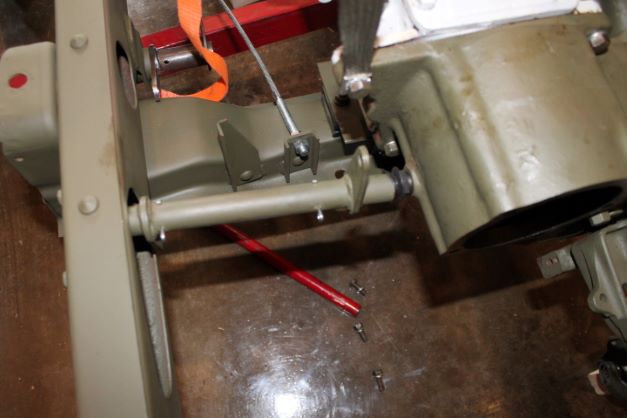
- Install the Clutch Control Lever Tube on the two ball studs on the frame and rear of the Transfer Case while you can swing the pack gently around.
- Lower the pack onto the round transfer case insulator and install the bolt wthtout lock washer finger tight.
- Continue lowering the pack onto the mounting plate and install two forward mounting bolts with L/W finger tight.
- Reposition the pack to allow the right rear mounting bolt to go in finger tight
- install the left rear bolt with two star lock washers and grounding strap as discussed in the electrical section.
- Tighten each bolt a bit in sequence so as not to ruin threads.
- Remove the nut on the rubber insulator, install the L/W and then tighten the nut back down.
You probably noticed all the Lime Green Tape on many components! Those are my small lists of things to complete such as: re-torque, install drain plug, grease fitting, install cover etc. Anything I fail to do that is a small detail is added to the tape and stuck on the component.
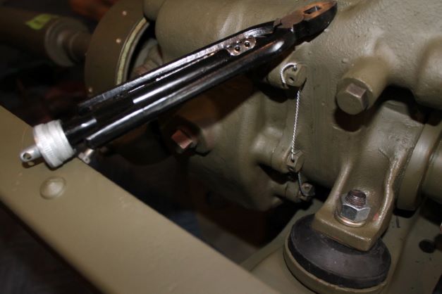
Safety Wire on the Front and Rear Bearing Caps
I purchased an aviation safety wire twist pliers. I am glad I did this as the twists look uniform and neat. It was relatively easy to do even with the bolts hidden behind components. I should have done this before installing the TC.
