Jeep Radio SCR-694C
General Information
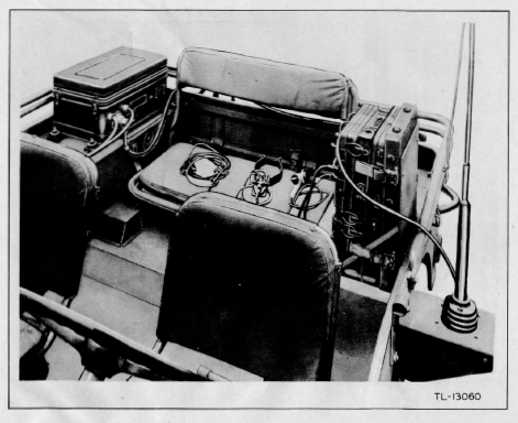
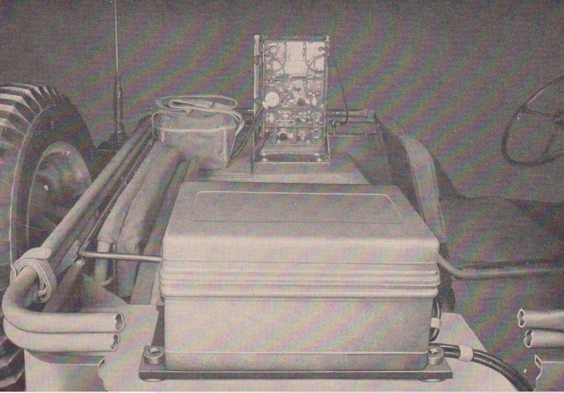
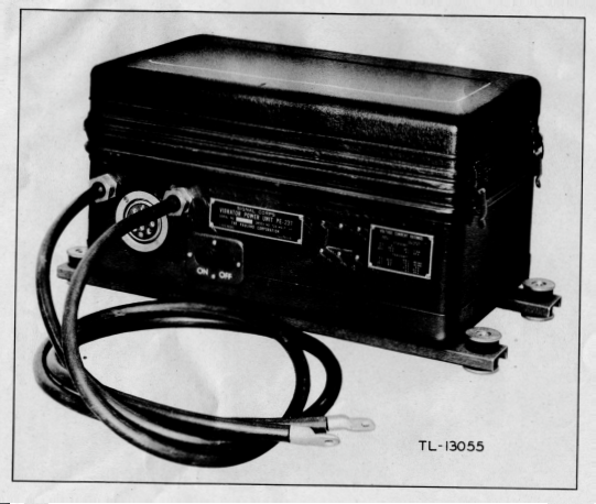
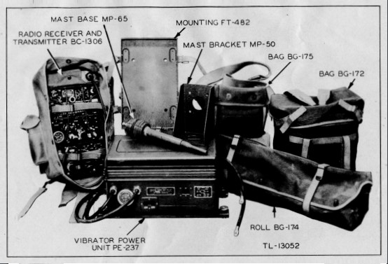
During 1944 a new radio was released by the US Army for installation in vehicles. The SCR (Signal Corps Radio) 694-C consisted of a radio, the BC-1306 and a pewer source, the PE-237. Along with these two components came a host of other items to make the radio either man-poratable or suitable for installation in vehicles. Engineer combat units seemed to be one of the recipients for vehicle installation, as they show up in the Table of Organization and Equipment for a few differnt engineer elements. This set up will be suitable for display in the 139th Airborne Engineer Battalion GPW. The installation TM was not issued until mid-1945, and there do not exist many images of this radio installed in war-time vehicles. Its use was more wide spread during the Korean Conflict.
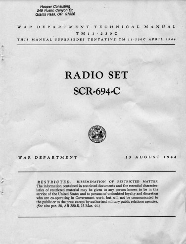
TM11-230C
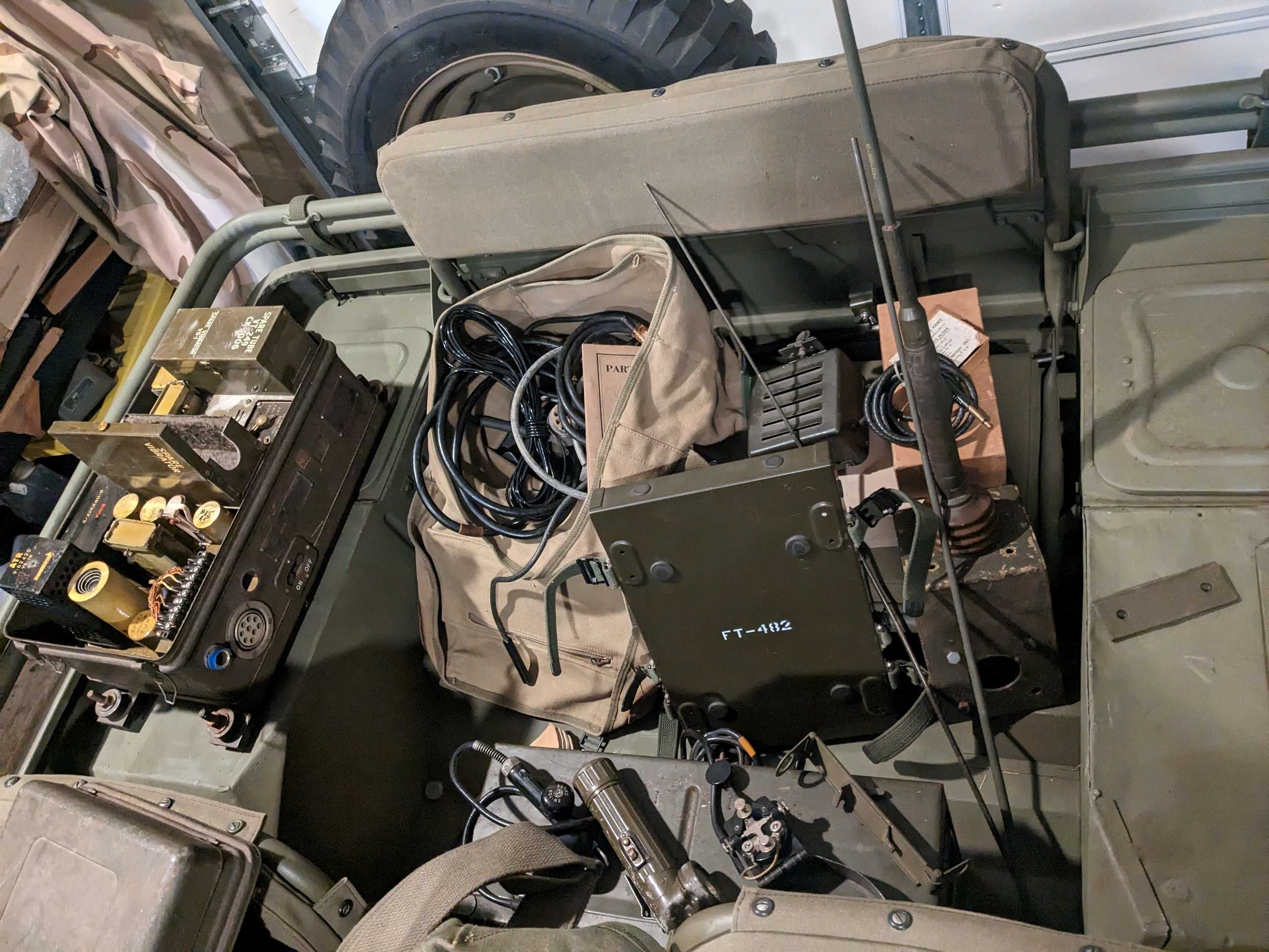
TM 11-230C, dated April 1944 contains all the information needed for the operation and unit level maintenence of the components of the radio set.
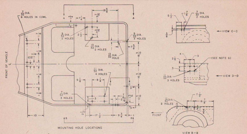
TM 11-2715, Change 2
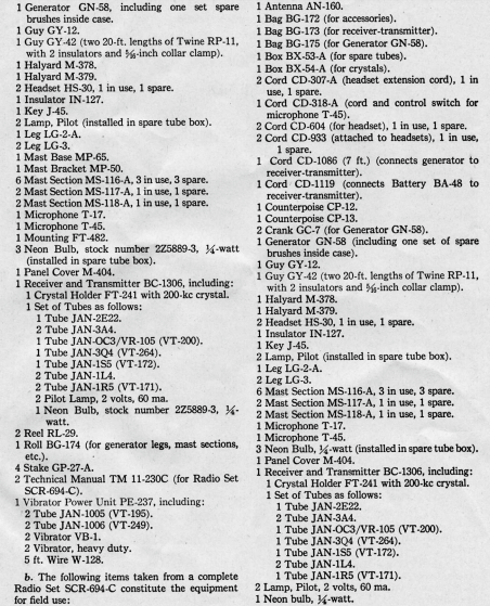
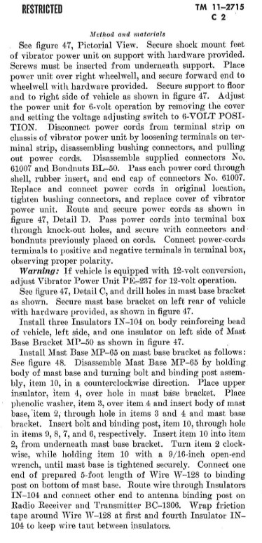
Change 2 to TM 11-2715, Dated 26 January 1945 provides detailed instructions for installing the SCR-694C in a 1/4 Ton Truck. The pages provide drilling hole locations, and detailed step-by-step instructions for how to istall the many components of the set into a GPW. I will follow those closely, making provisions for lack of original materials as required. The instructions are very detailed and it helps to study the parts lists and diagrams before starting.
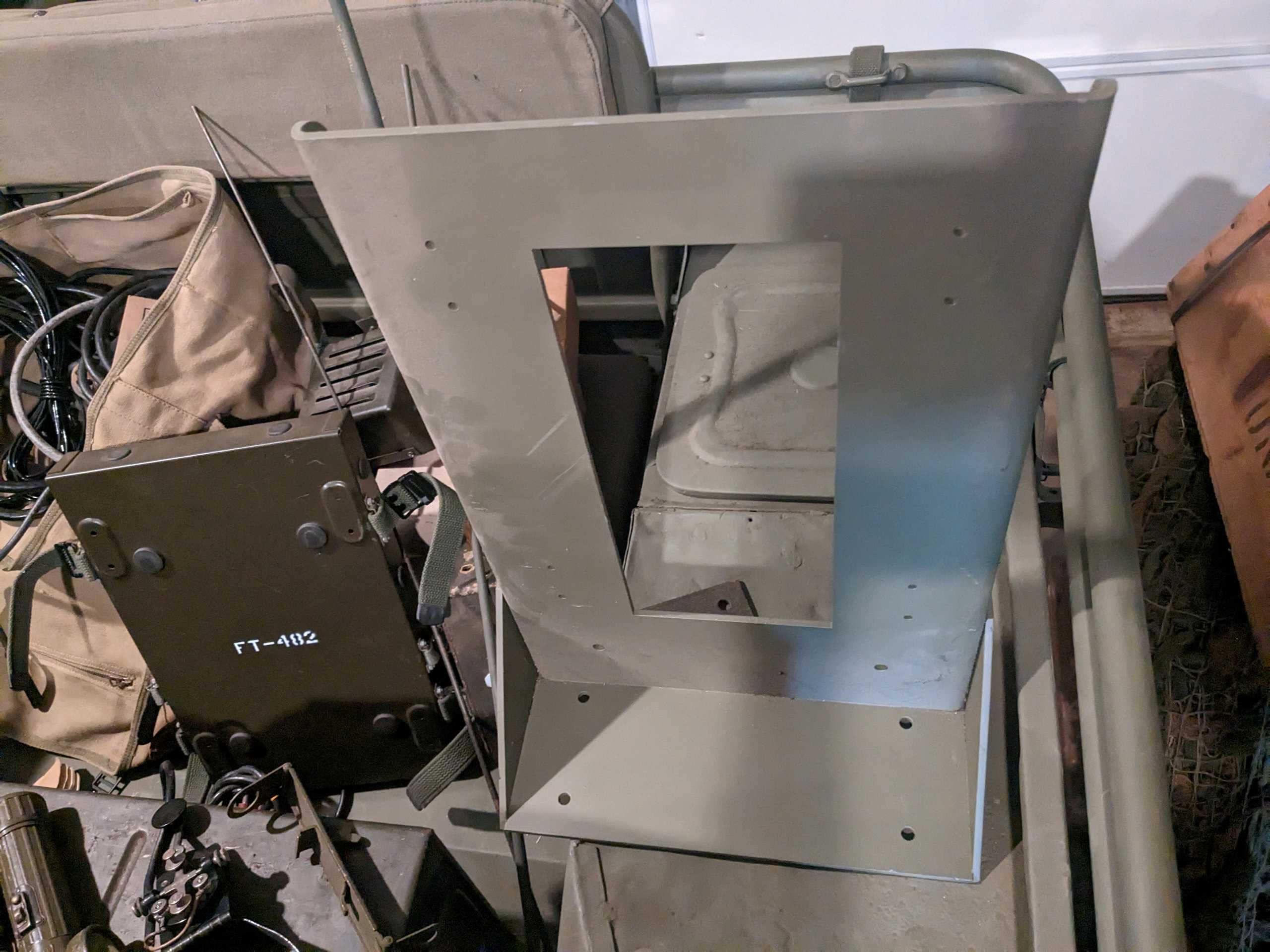
Before Installation
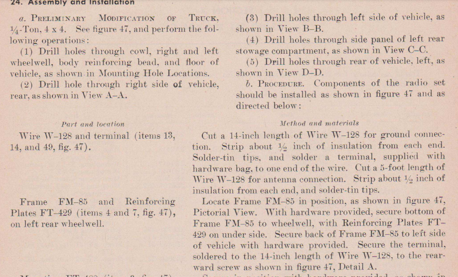
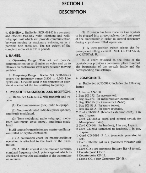
I spent a good bit of time before starting the installation reviewing the instructions, gathering components and test fitting everything. Much of the NOS hardware is no longer available, and new replacements are needed. I have spent the last 2 years collecting cables, mounting brackets and the radio accessories. The list of required items is very extensive and is copied at right from the TM.
Hole Drilling
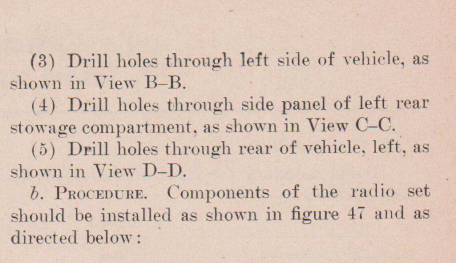
The instructions direct the user to drill all of the hole locations as shown in the TM diagrams. I will drill holes one component at a time, rather than making all of the holes to begin with, just to make sure everything is correct.
Installing the BC-1306 and Frame Components
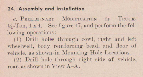
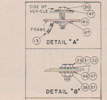
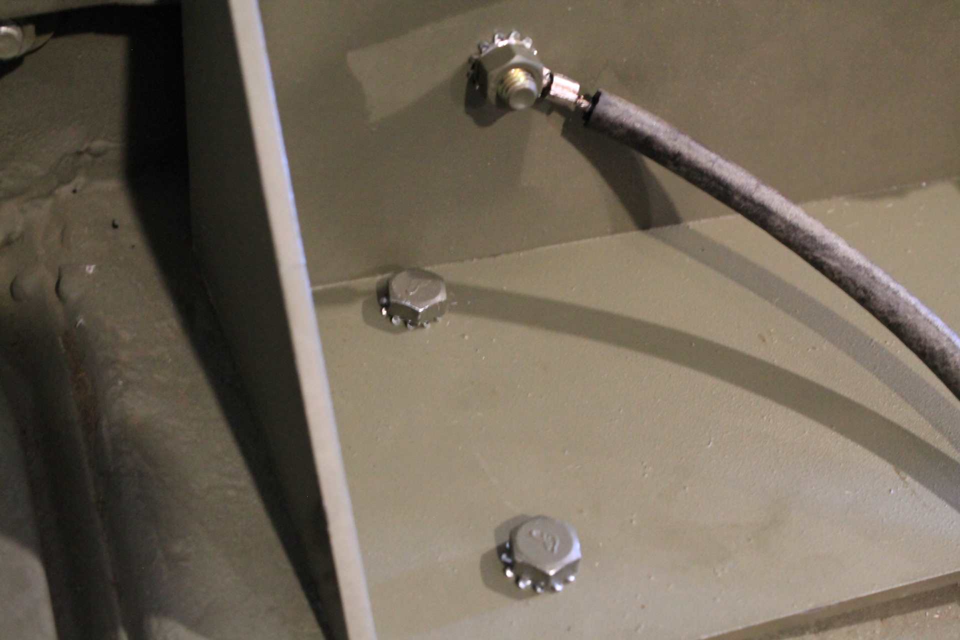
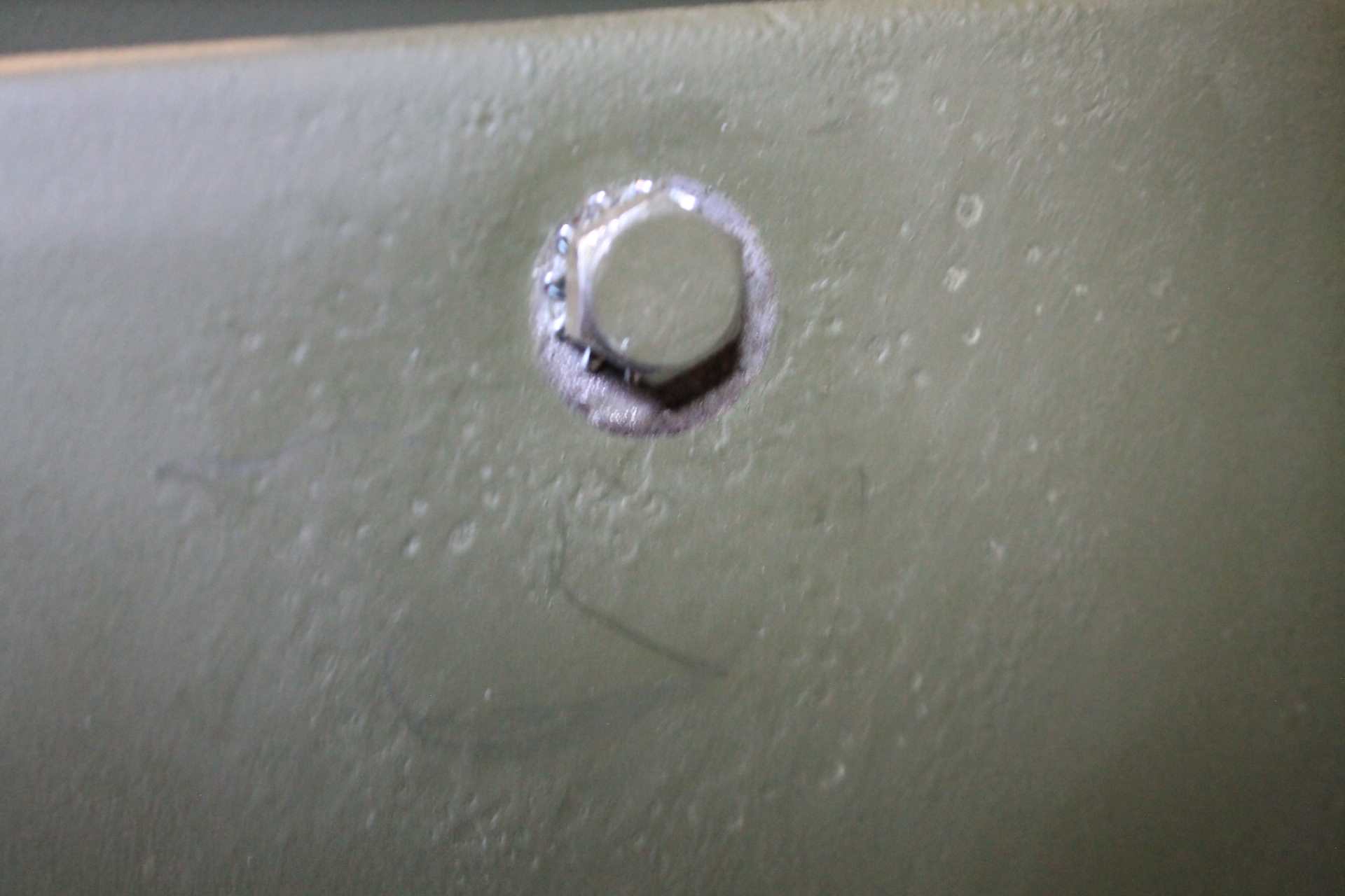
I acquired a length of original W-128 wire from a collector in Italy. Two pieces are required for this part of the assembly. I started by preparing the ends as indicated. I then placed the FM-85 frame on the left rear fender in it's approximate position as indicated in the hole drilling diagram. 4 holes are located to secure the frame to the fender top, and 2 holes to secure the frame back to the side lip of the tub. The holes are 11/32" diameter holes to accept 5/16 Hex head screws. The 4 screws are 1" long, and the TM indicates the side screws at 2", but I found 2 1/2" to work better. Each are attached with 2 external tooth lockwashers, although the TM calls for Internal-External type. Note the length of W-128 is attached to the rear-most bolt that passes through the tub side as shown in detail A to the right.. I placed the terminal end between the lockwasher and the nut. This will allow the lock washer to dig into the tub metal and make a good ground. I lightly tinned that hole location on the outside of the tub. Detail B shows the washer and bolt stack for the 4 bottom screws. The radio and cover are then installed per instructions.
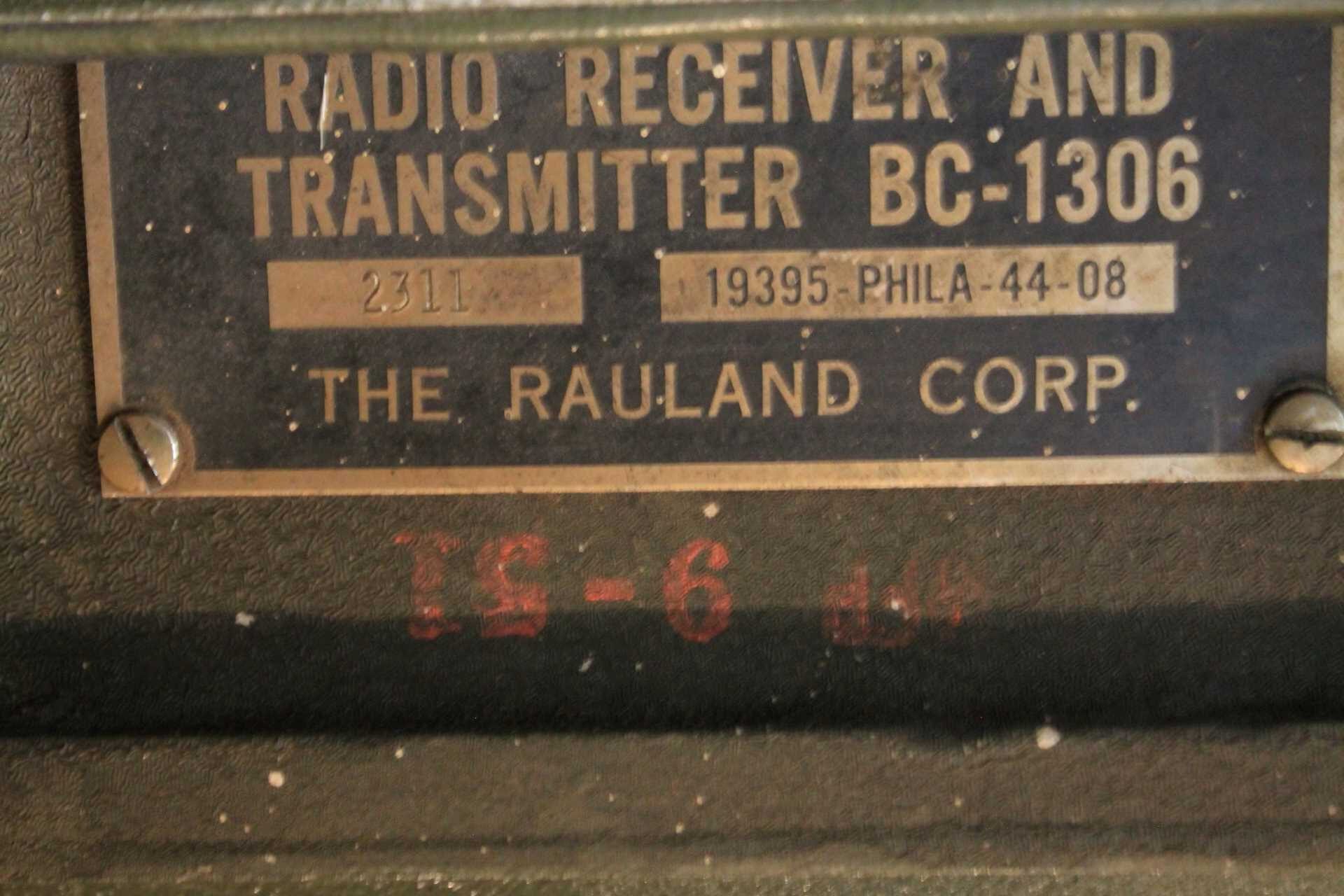
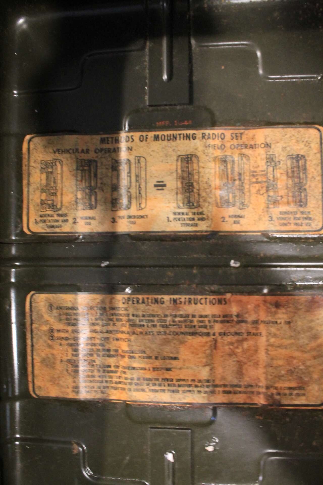
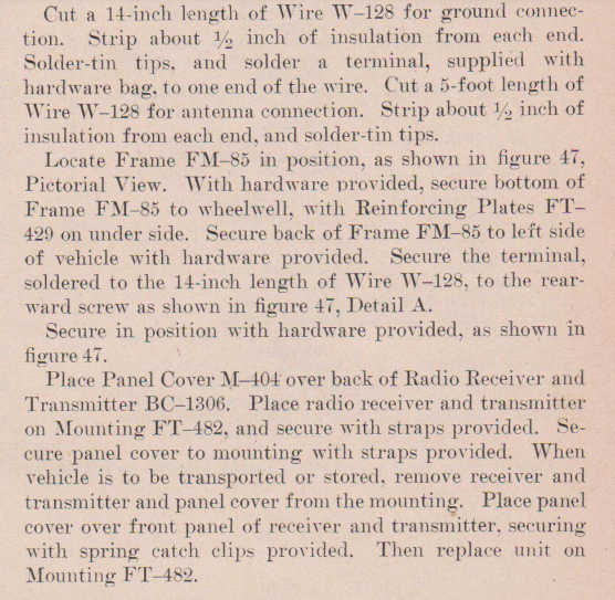

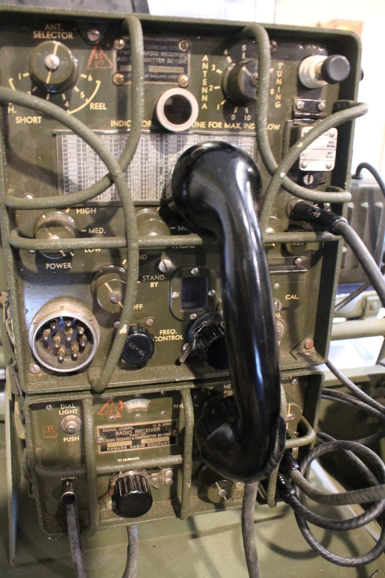
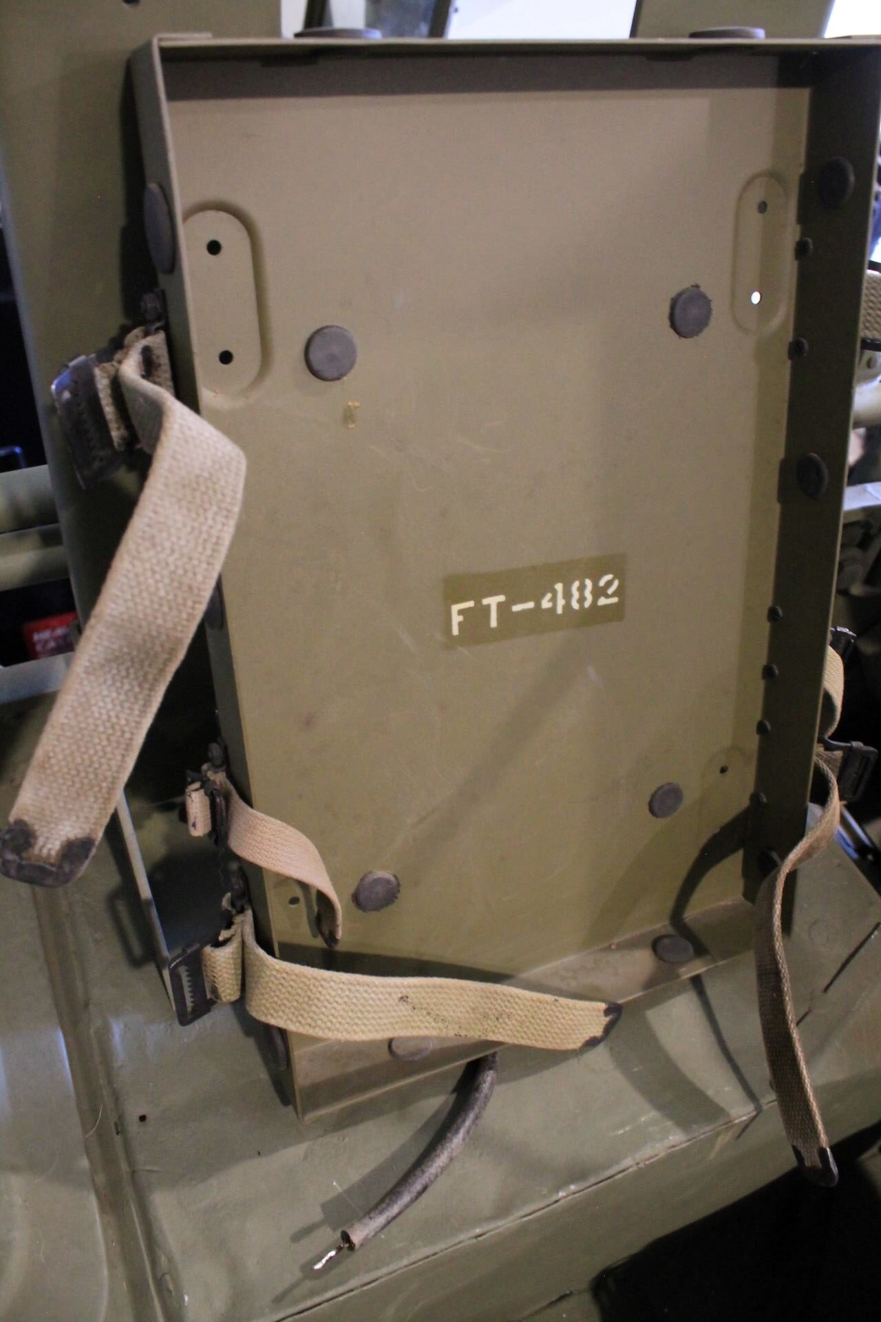
The TM calls for eight #8-32 x 3/4" screws, lockwashers and nuts to secure the FT-482 to the FM-85. The Screws seem longer than required and have to be mounted with the heads on the inside and the threaded portion sticking out of the back so that the cover will fit into the mount. I found some vintage slotted screws to use. I secured the cover to the back of the BC and used the 6 straps to hold the radio securely in the mount. Just to check the fit I attached the jacks from an LS-3 and a handset into the respective sockets. Fit seems good. I connected the W-128 wire to the BC-1306 grounding post.
"Mount" for PE-237
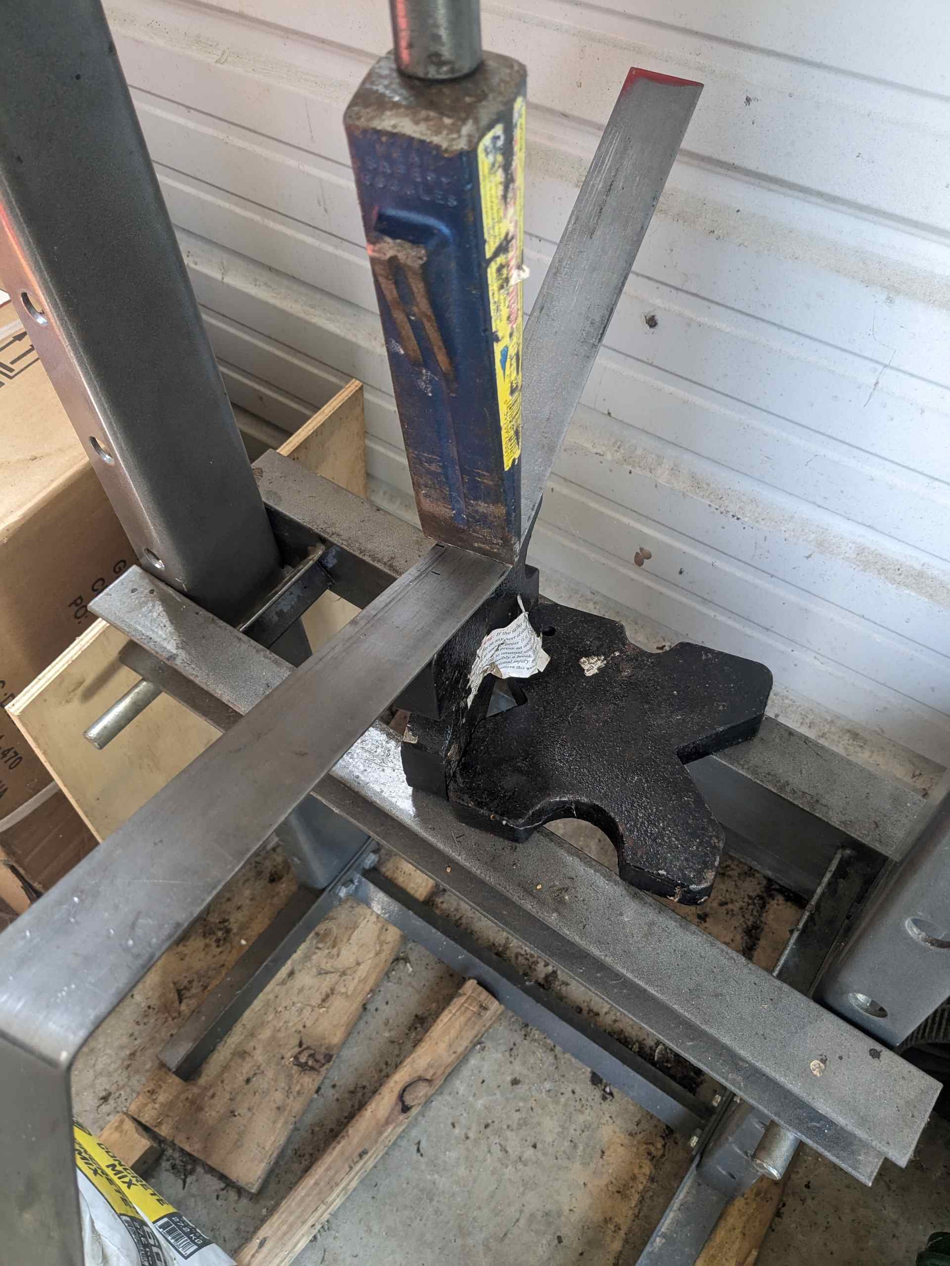
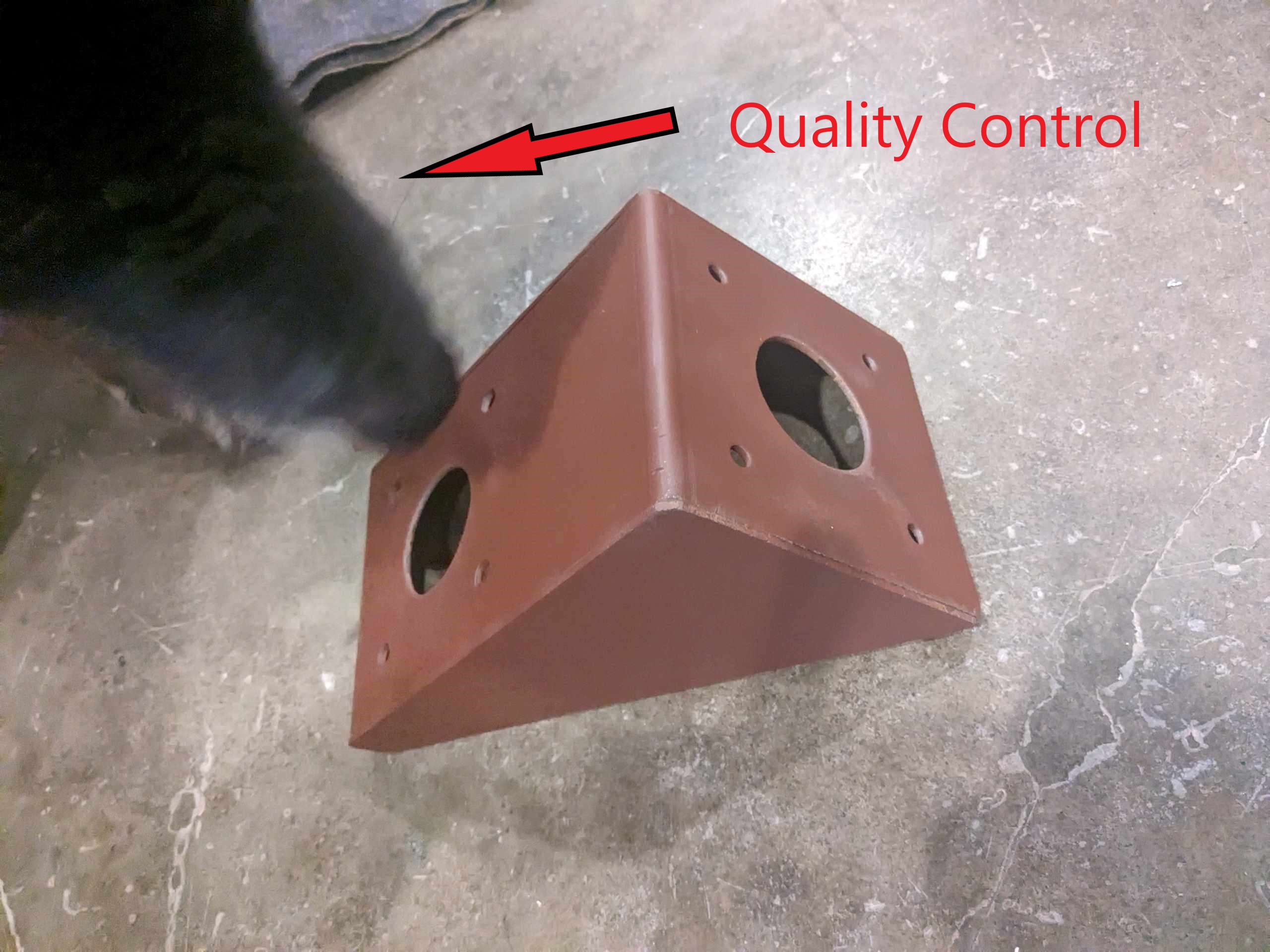
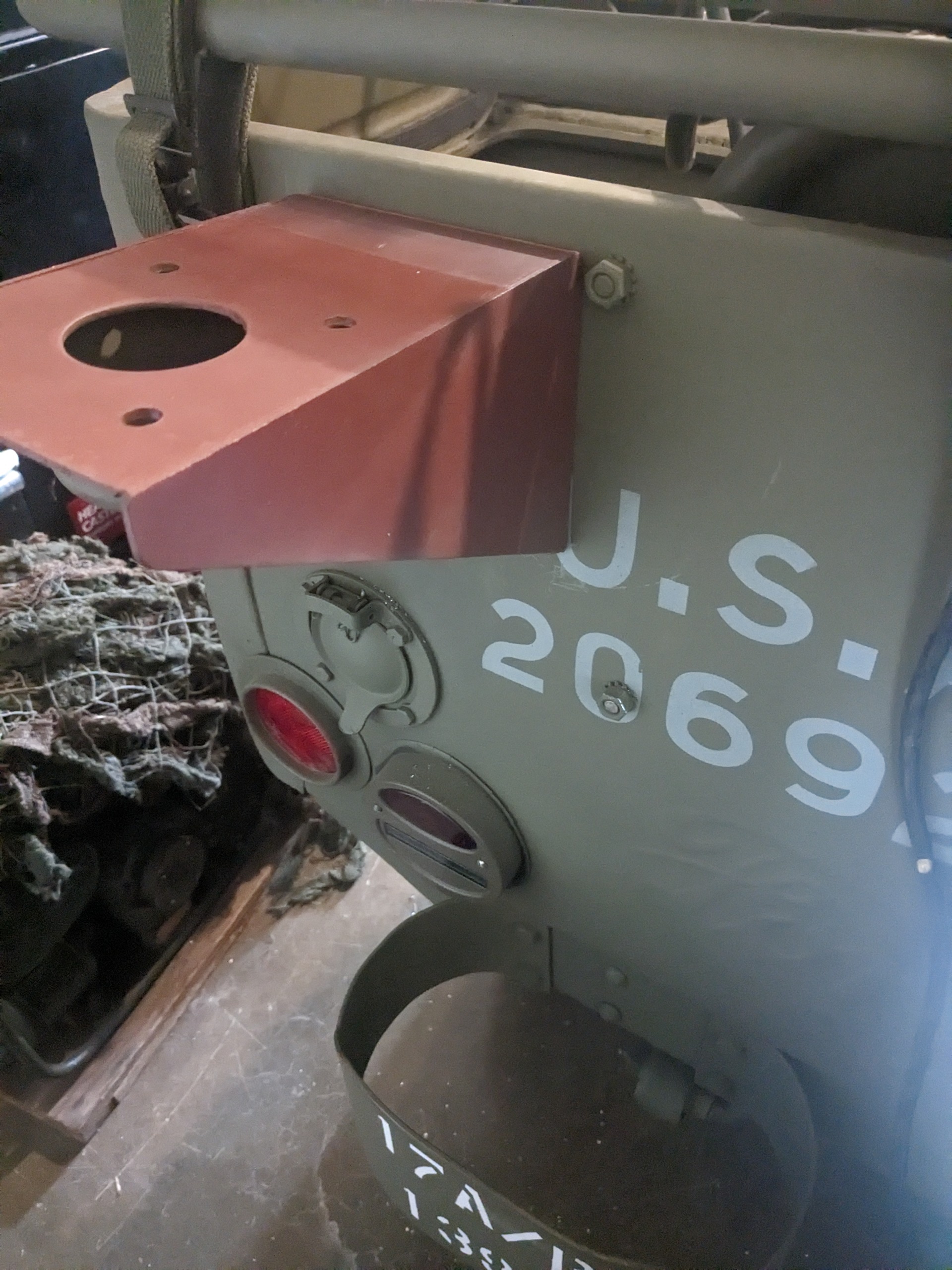
I could find no specifications or drawings for the mount that secures the rear bumpers of the PE-237 to the tub. I used 3/16" mild steel and bent it to a profile that follows the contours of the fender and tub as shown in the images in the TM using my press. I drilled 13/32" holes for the 3/8" bolts that secure the PE to the mount and the mount to the tub. I debated using 1/4" as it would be easier to bend, but elected with the more sturdy 3/16" as the PE is about 50lbs. AFter bending the mount was primed and painted. I did not use the wrinkle finish as all of my original mounting hardware is finished in flat olive drab.
Installing the PE-237
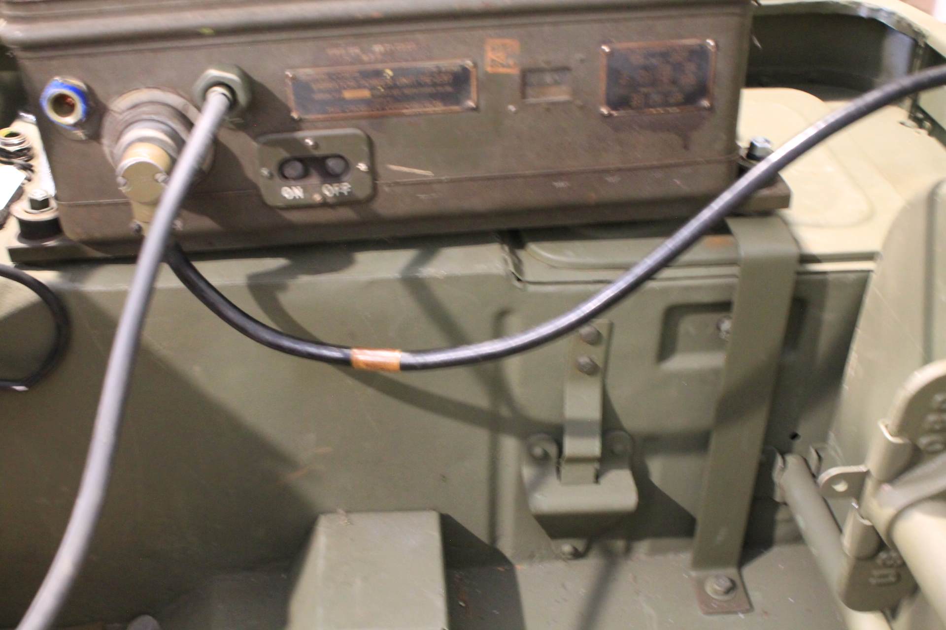
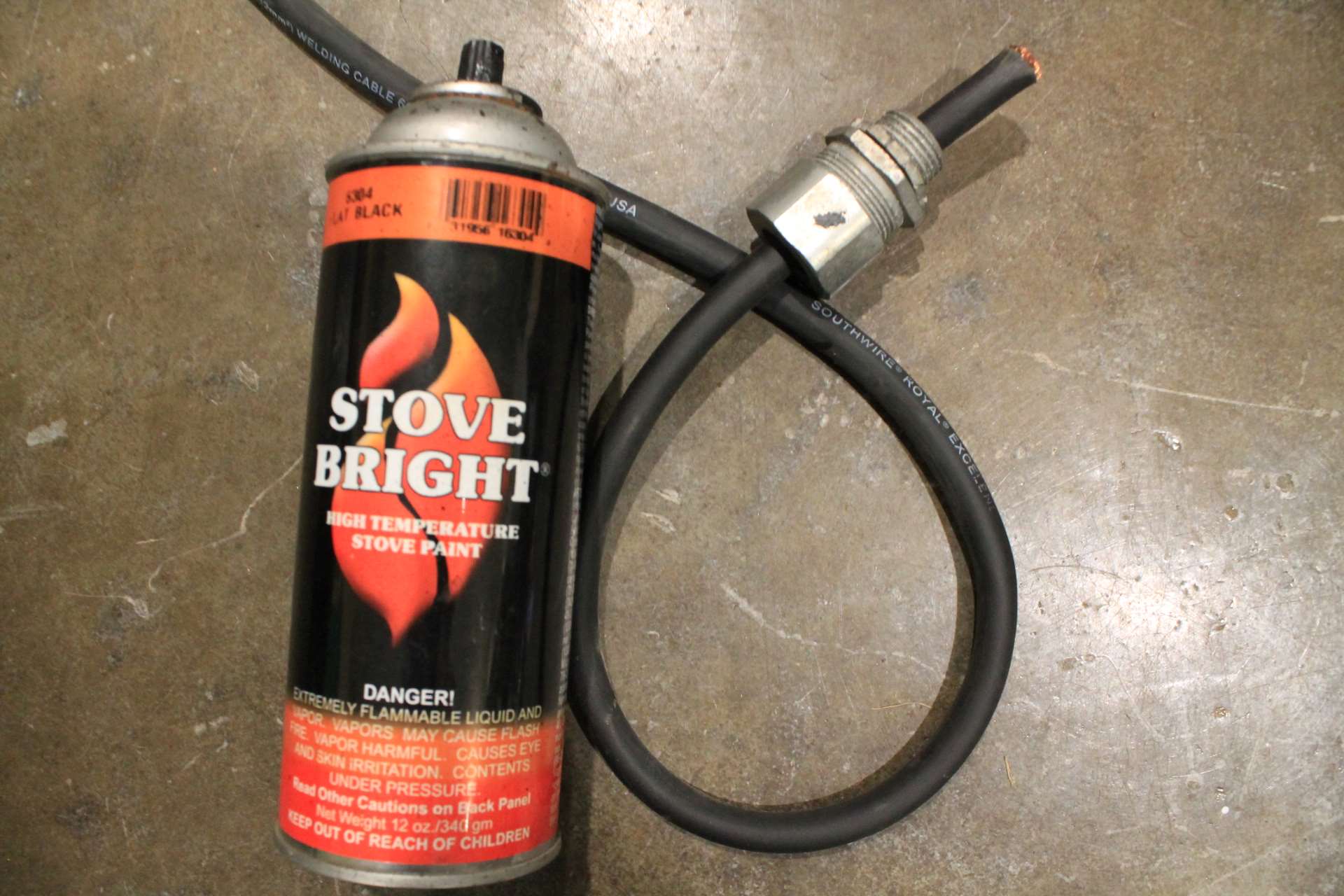
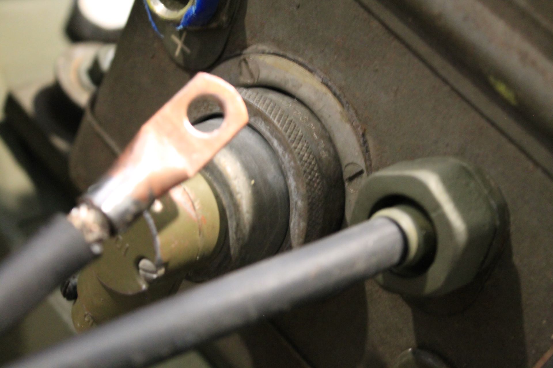
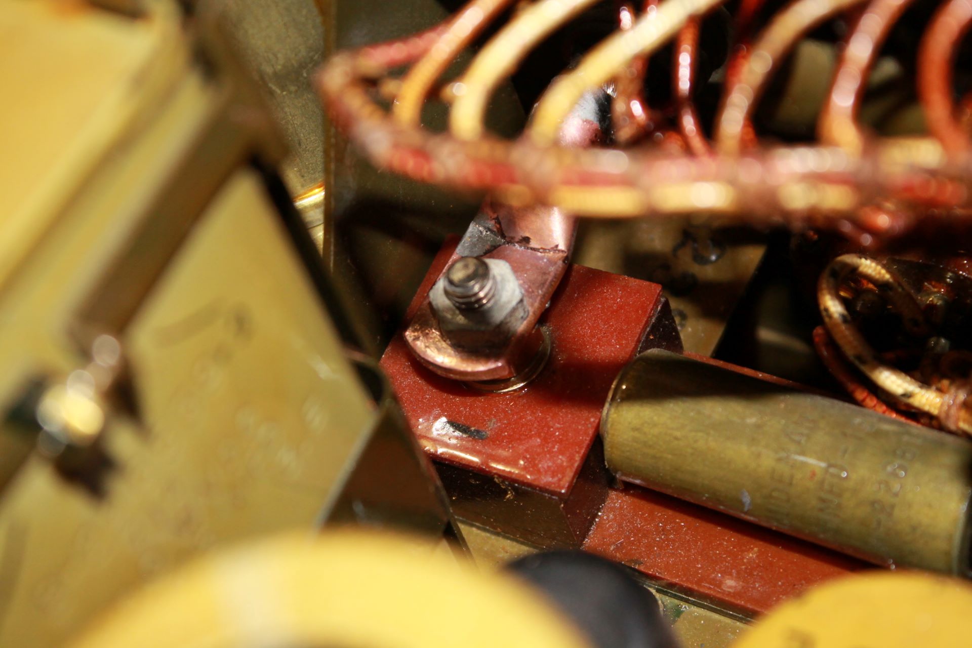
My PE-237 did not come with the postwar cables or the cable binding nuts. I ended up purchasing some No. 2 Welding cable and used Stove Bright spray paint to mask the modern cable annotation. It seems to work good and does not create a skin on the cable and matches the sheen. I found two cable binders in my stash of radio parts. Lucky me!
I secured the copper connectors to the welding cable and ran them through the cable binders and secured them to the post.
Mast Base MP-50
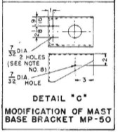
I had a take-off mast base. I sand blasted the various coats of paint off, primed and painted it. I mounted it in accordance with the instructions. Based on Detail "C" this mast base has been modified for the MP-65 and is installed with the long surface in the horizontal orientation.

MP-65 Mast Base and Antenna
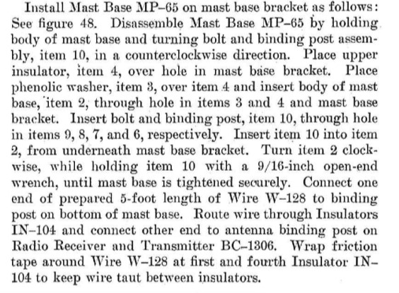
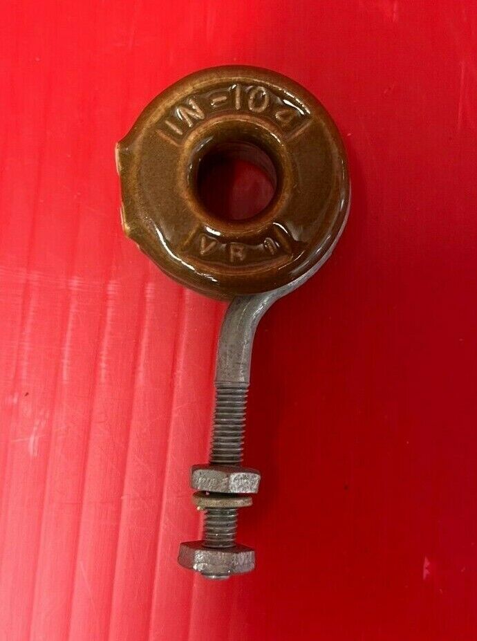
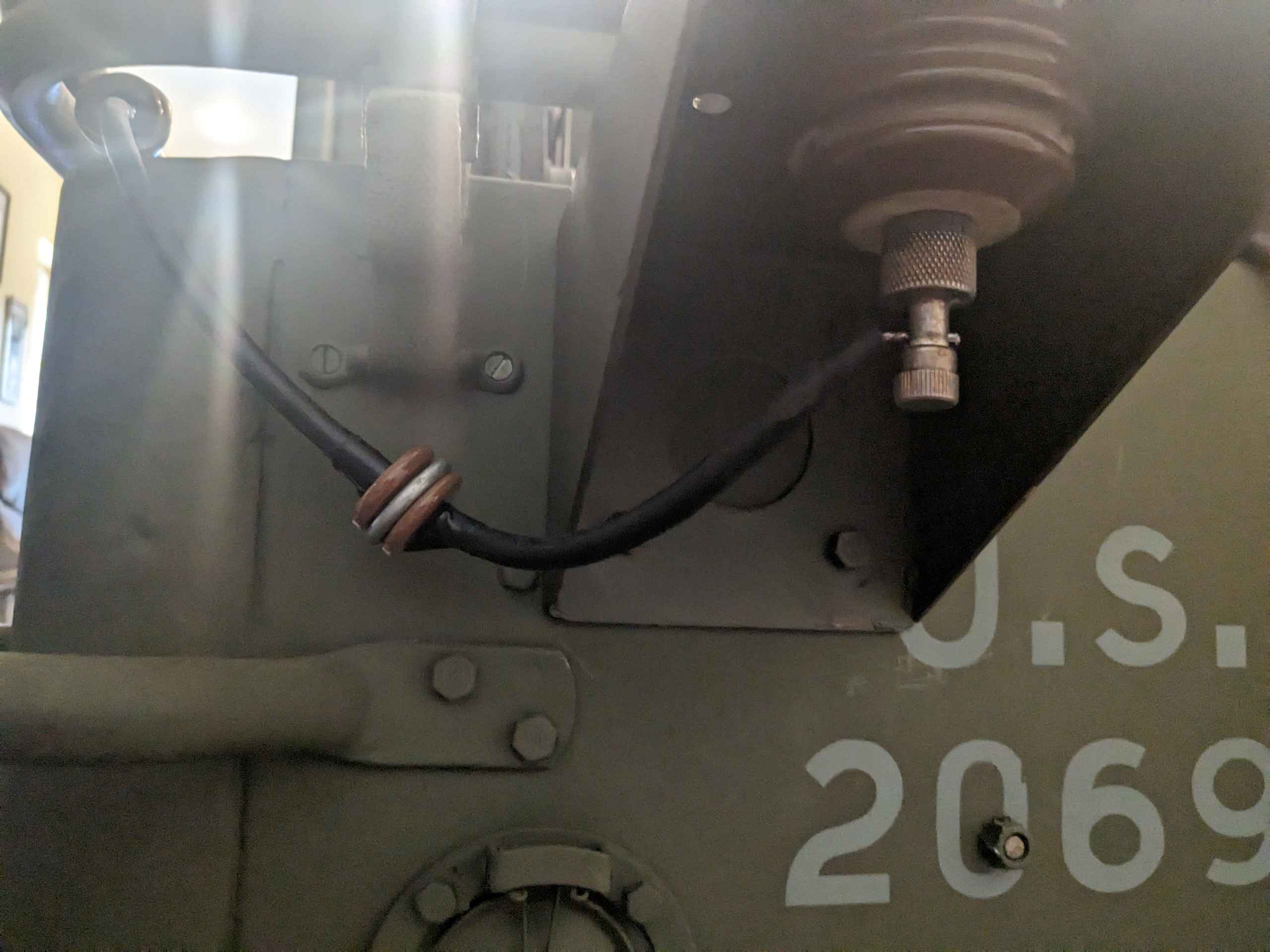
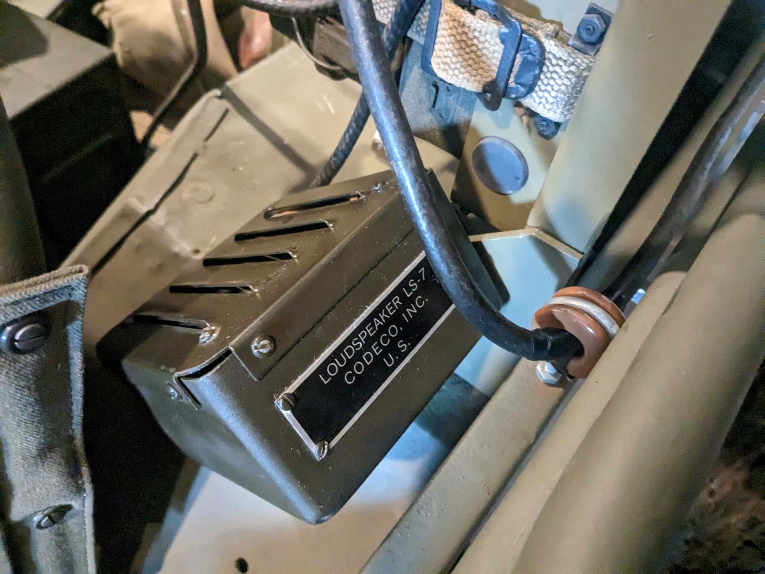
I installed the MP-65 Mast Base with wire following the instructions. I had to find 4 of the IN-104 Insulators that keep the antenna wire lead off of the body panles.
Pending
Pending
Pending
Pending