Engine Assembly
BEFORE
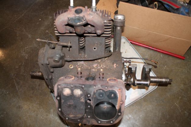
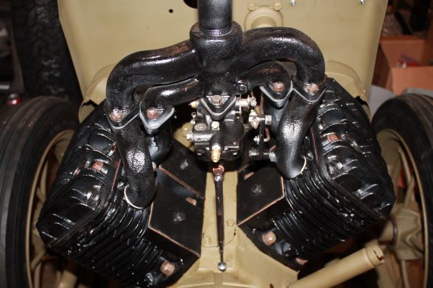
AFTER
Priming the Block
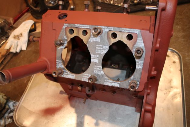
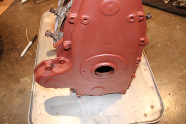
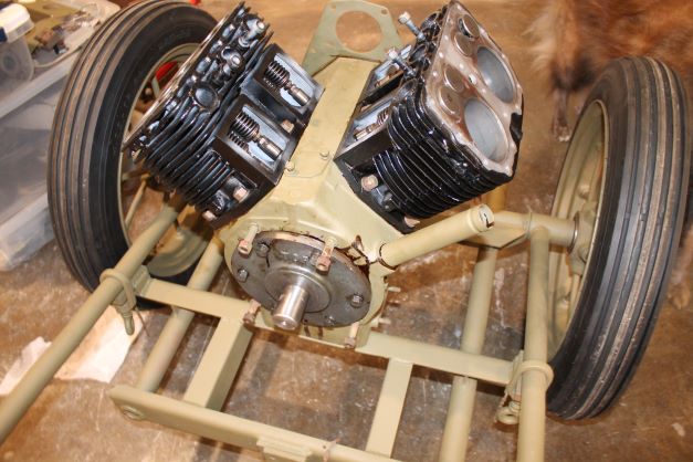
I thouroughly cleaned the engine block and the timing cover and then primed them with red oxide primer. The timing cover is simply held on for now with two bolts
The cylinders will get a coat ot two of VHT black and the rest will be done in OD
Cylinders, Manifolds and Head
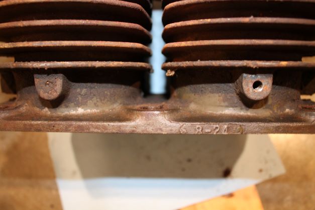
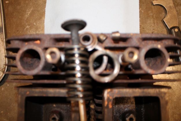
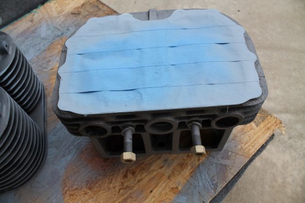
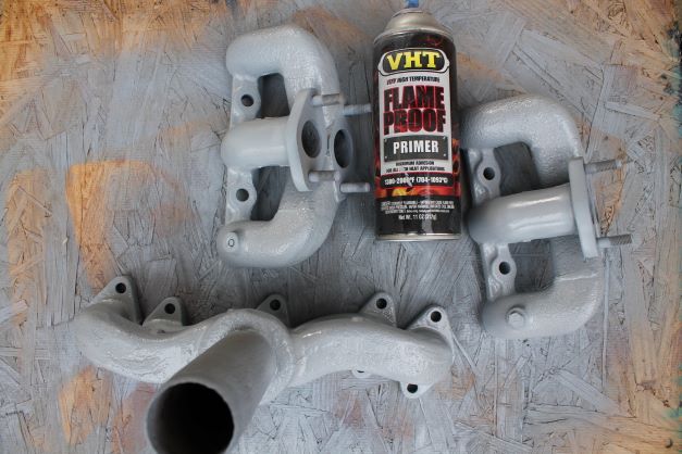
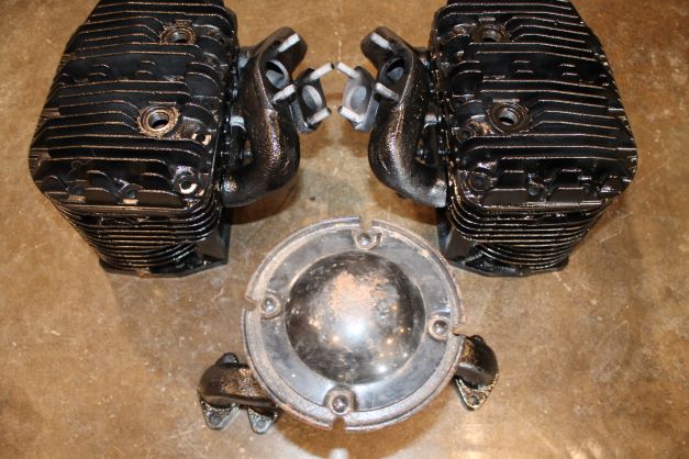
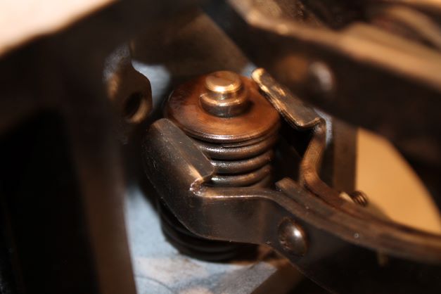
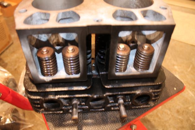
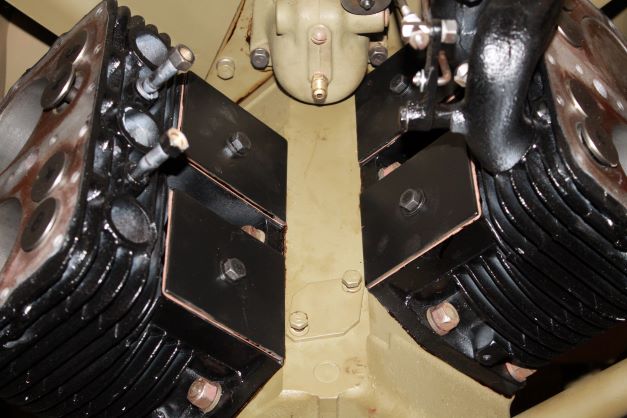
The cylinders and heads are very grungy. I will clean them up and use a blck VHT to paint them. I could not tell during tear down what the original color was I assume black or OD. The cylinders have a manufacture date boss. One shows 8-24, the other 8-25 for August 24th and 25th. Just like the HD WLA cylinders, I have to find out how the year is determined. Here is an image of the valves, springs and keepers. They used all EX valves, so I assume a rebuild at some point. I'll take the cylinders, heads and manifolds to get blasted. I blsted them, Masked the mating surfaces using an old gasket with tape, primed them with VHT primes and opainted them in semi'gloss black to match the NOS muffler.
Valve Grinding
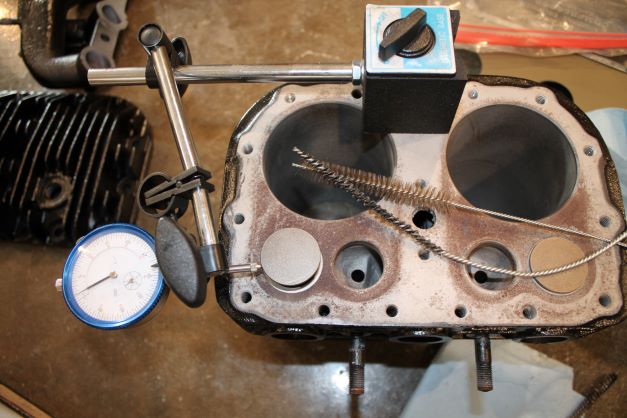
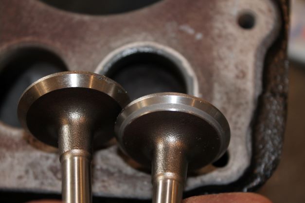
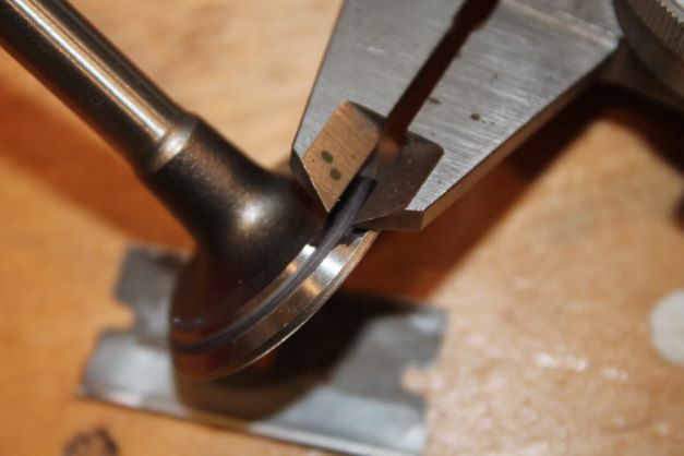
The 8 valves in the engine were all hardened exhaust valves. Many of them were in poor shape, so I opted to purchase 8 new Federal Mogul exhaust valves. I cleaned up the guides with cleaning fluid and stiff brushes, removing all the grime and carbon. Once each valve slid down on its own weight I moved to the next.
Once this was done I checked the clearance between the valve and guide. 5 of the valves were less than the maximum of 0.005" and at the minimum of 0.003" Two valves were slightly out of tolerance at 0.007" and one at 0.10". Since this is not going to be a daily use machine I am not planning on replacing all of the valve guides.
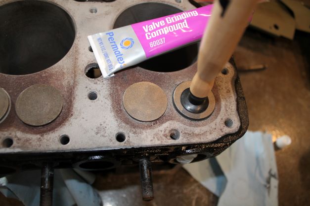
I tried the suction cup grinder and found it a total flop. I used my thum and index fingers of both hands, one hand to rotate the stem and one to help rotate the valve face while applying a slight downward pressure. I rotated back and forth 3 times, rotated 90 degrees, repeated and did this about 20-25 times. I then began a constant rotation using the same method until the feel went from a gritty feel with a sort of raspy sound to a smooth feel and paper-sliding-on-paper sound. That told me the grit was expended so I raised the valve, introducing a bit more grit and repeated. I did this about 5 times and you can actually feel the face of the valve meshing with the seat and it sounds and feels very smooth.
I also used a 45 degree seat cutter and cleaned up the seats.
Cylinder Honing
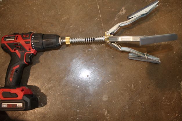
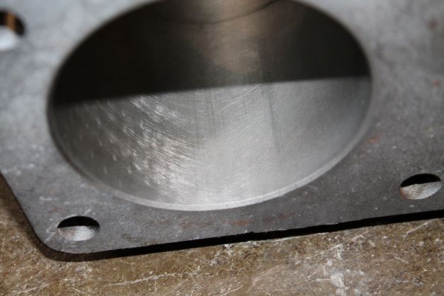
The cylinder walls appear in good shape, are standard size and have no large scratches or ring marks. I am using a simple Laguna brand cylinder hone and a battery operated drill to get a 45 degree-ish cross hatched pattern in the cylinders. I cleaned them up and with the hone at the lowest tension setting made about 15-120 up and down passes trying to achieve that 45 degree pattern. here is the result.
Installing Lifters
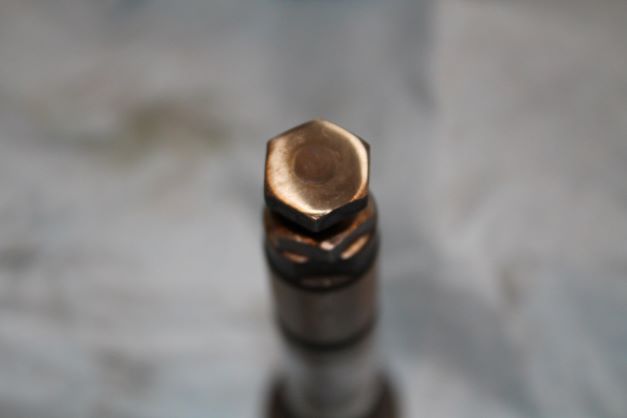
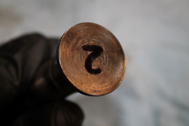
Each of the 8 lifters were cleaned and lightly polished, given a coating of assembly lube and inserted into their marked hole. They were in excellent shape with a mild bit of flattening where the old valve stems made contact. I am not going to worr about this.
Installing the Cam and Spacer
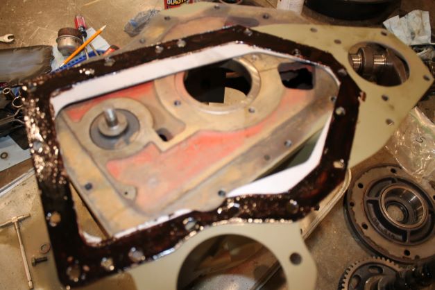
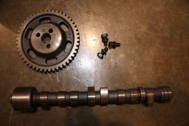
I cleaned the mating surface between the spacer plate and the block, double schellacked the gasket and secured it with the 5 screws and star washers. Those were torqued to 17.5 ft/lbs. The cam is in excellent shape. It was cleaned, hand polished and received a coating of assembly lube on all rotating surfaces before being inserted with the block sitting on the output end to keep the lifters fully extended out. The Cam gear will be installed later, but you can see the plunger and spring in place. The TM calls for the spacer to be installed later, after the cylinders are in, but I cannot see why that will matter.
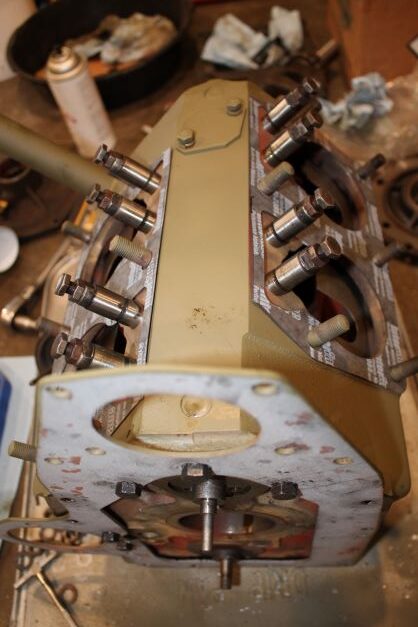
The next step outlined in the TM is to install the valve springs, keepers and locks and install the cylinders onto the block. The gaskets provided are fairly thick, but I will give them a light coat of shellack on each side before installing the cylinders.
Valve Springs, and Keepers in
Very simple but tedious task getting all 8 of the springs and keeprs in in their original configuration 1 thru 8 as originally installed.
Installing the Cylinders
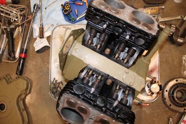
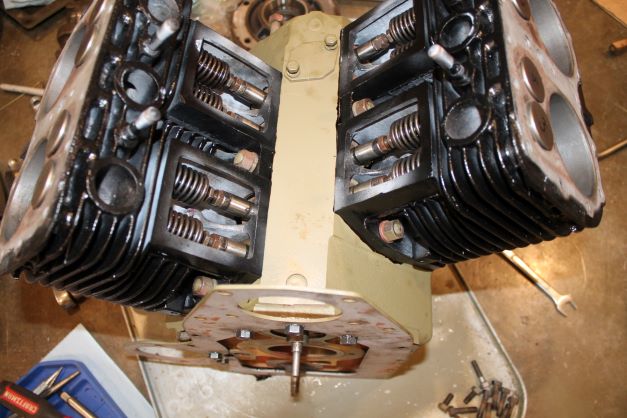
Nothing special to report here. I simply installed the gaskets with aviation sealer and torqued the bolts down gradually to seat the cylinders in place.
I do have a bit of black and OD paint to touch up later.
Setting the Tapper Clearance
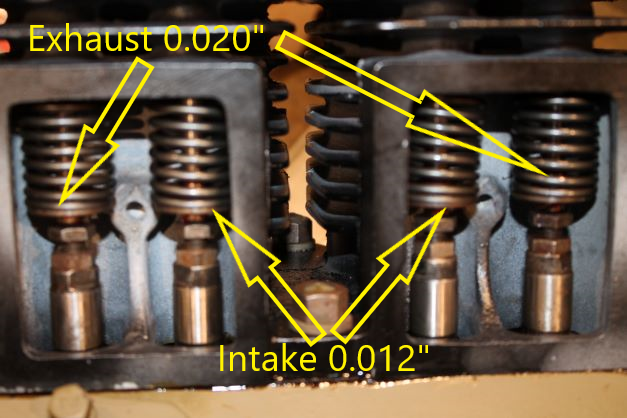
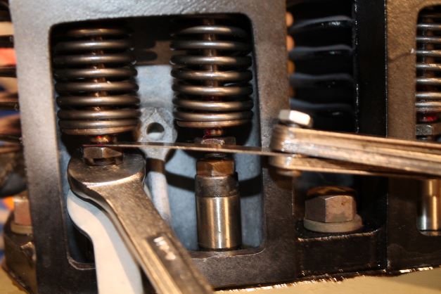
While I am at this point I set the gap for the exhaust tappers (as the TM calls them) at 0.020" and the intake at 0.012" COLD.
Installing Rear Bearing Cap and Crankshaft
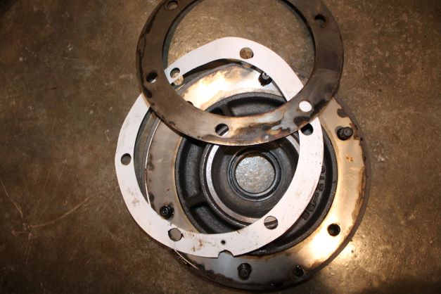
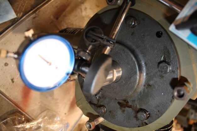
I followed the TM to determine the amount of shims needed to obtain 0.003' - 0.005: endplay. I had a problem getting a consistant reading with the feeler gauges so I started with the original shim pack minus 0.010" shim as I was using paper gaskets between each set of shims that weren't in there before. That might account for why so much oil leaked out on the output side.. The first measurement yielded 0.015" end play. I was using 20ft/lbs torque on the cap, so adding 5 pounds only changed it by 1 thou. I removed a single 10 thou shim and rechecked coming up with just under 0.005" end play at 20 pounds. I am happy with that process.
Piston Rings
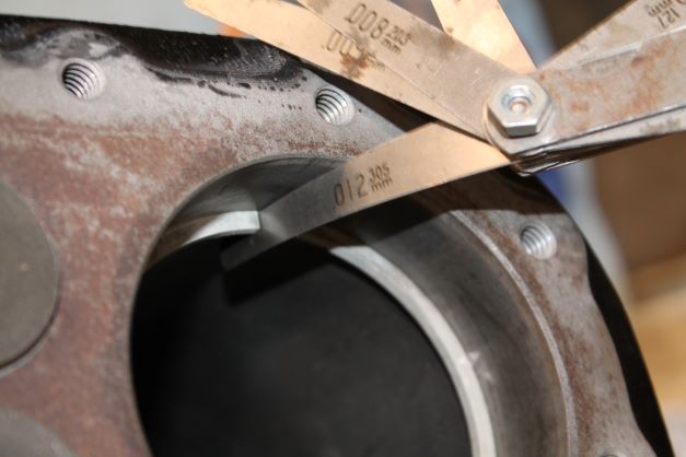
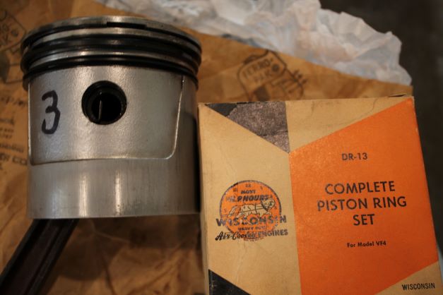
The gap in the piston rings I had were well over 0.020" The spec is 0.010-0.020" I ordered an NOS box of VF4 rings for standard cylinders. They installed properly with an average gap in the cylinder of 0.012". I cleaned up the 4 pistons and installed the rings and checked the spacing in te groves per spec.
Install Pistons
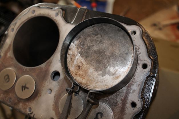
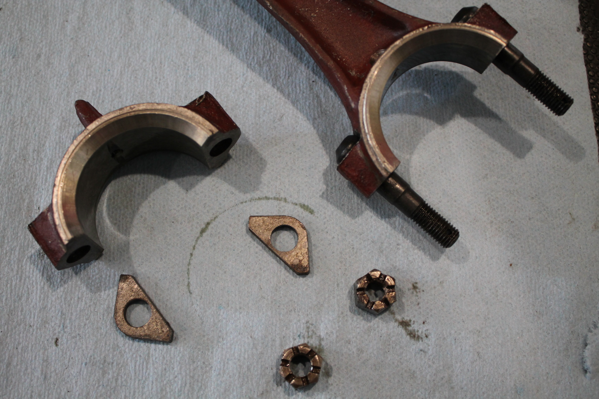
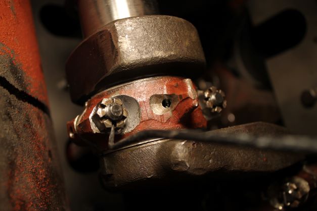
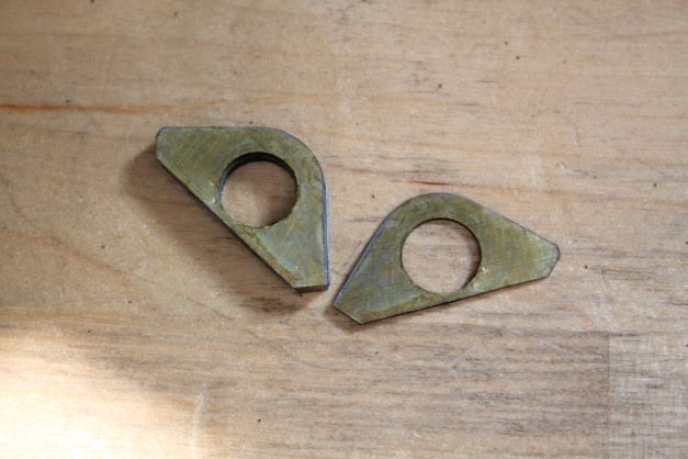
I kept all of the spacers, caps, bolts and catle nuts on the same piston in the same configuration. I used a piston ring compressor and slipped the pistons in one at a time after oiling the cylinder walls and rings again. I used assembly lube on the crank journals and bearings. The cotter pin holes are perpendicular to the axis of the rod juornals and were fairly easy to find and insert the pin. I could not get a torque wrench even with an extension into the block to set 23 ft/lbs, so i used feel and made sure the nuts lined up for the cotter pins. I used plastigauge to check the clearance on the journals and had 0.002 which is at the upper end.
Engine Oil Pump
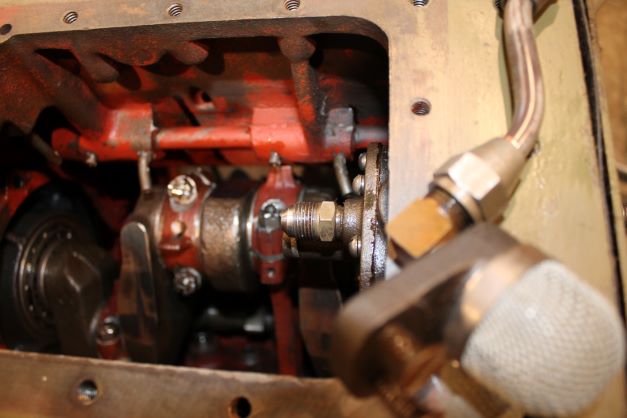
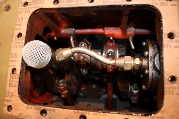
The oil pump has been cleaned and the gears installed and a new gasket sealed with No 3 and the 6 screws. After the pistons are all in and secured to the crank the pick up tube, screen and housing will be screwed to the inside bottom of the block.
Securing the Engine to the Chassis
Place holder
Installing the Timing Gears
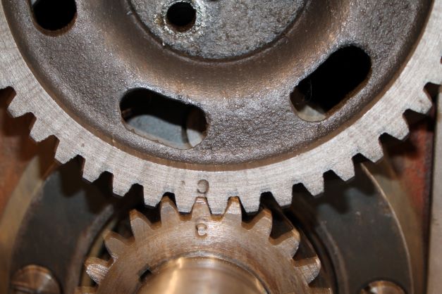
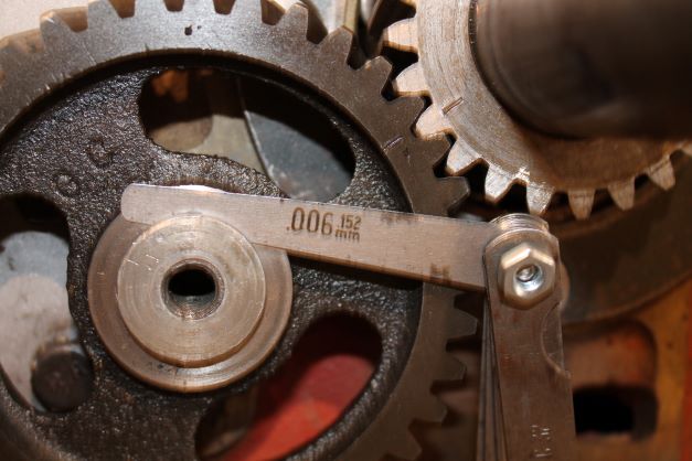
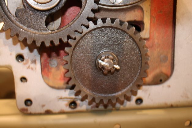
The engine crankshaft gear was turned so that the "C" mark is on top. I then installed the camshaft gear with the "C" on the gear in line with the one on the crank gear. WIth them lined up I was able to rotate the crank slowly so that the bolt holes for the cam gear lined up perfectly. I then inserted the 3 cam bolts and torqued them down. I indexed the gears so that the two "C's" were facing each other again. At this point the idler gear could be installed with the "I" facing the "I" on the crank gear. I then inserted the idler shaft and using a soft mallet drove it in so that "about" 0.006" of gear play existed between the shaft hub and the block. Then I installed the oil pump gear on the woodruf spline, tightened the castle nut and installed teh cottoer pin. I can now install the cover and gasket and later the governor and magneto gears will be installed.
Timing Cover Installation
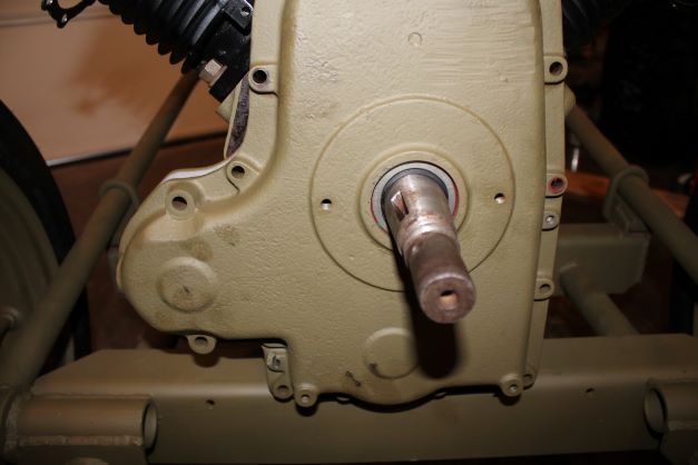
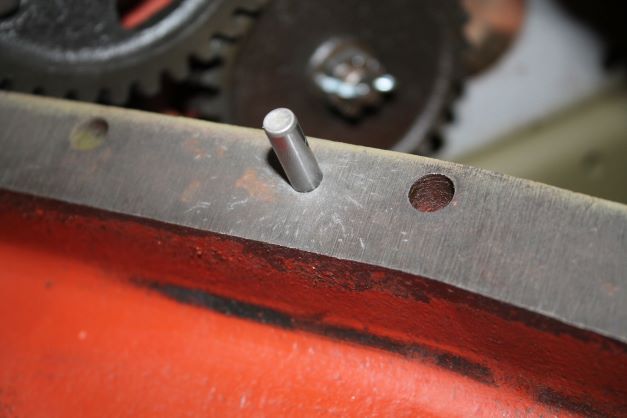
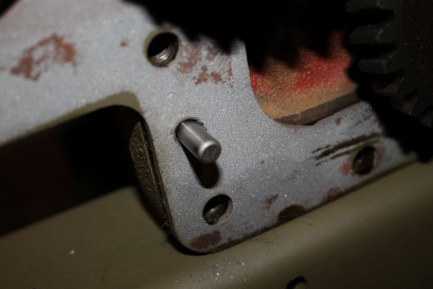
I had a heck of a time getting the 2 dowell pins out of the block and cover during tear down. I cleaned up the cover holes so that the pins were a slip fit of about 0.001" clearance and used a reamer to just open up the block holes so that I did not have to hammer the snot out of the pins going in. New gasket, 2 new pins, and it will be closed up. As a side note the cover has a new oil seal installed.
Governor
The governor is a fairly simple device to clean and assemble. I installed it with a new gasket and secured it to the top of the timing cover.
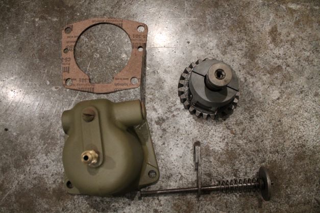
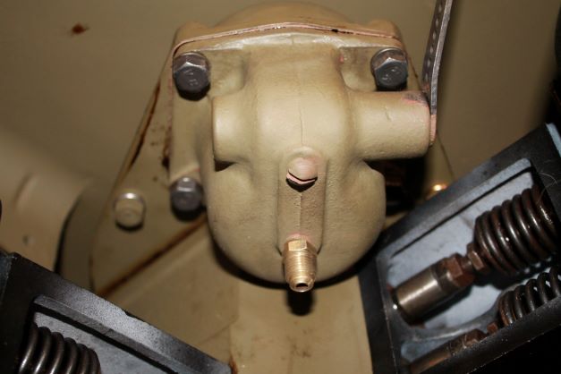
Speed Regulator and Governor Linkage.
The linkage for the speed regulator is connected to a bracket on the manifold. The TM shows the linkage going parallel from the bracket to the governor and speed regulator. On the actual engine the governor is below the line of the other link and so they cross. These were not hooked up when I bought it as the speed regulator was taken apart due to a torn diaphragm. Strange, but there is no other way around this that I can see.
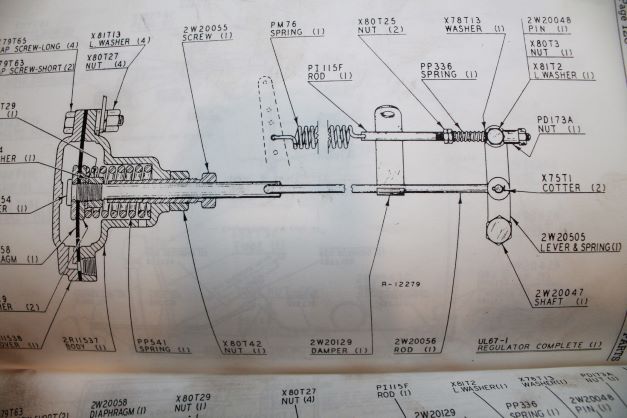
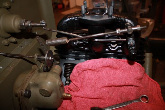
Valve Covers
Bolts, washers and new gaskets installed.
Exhaust Manifolds
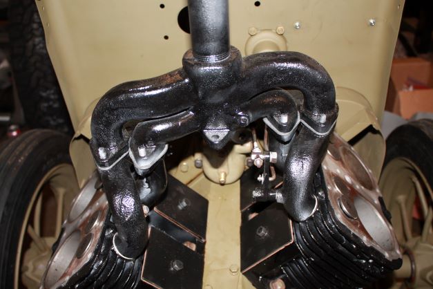
The manifolds were primed and then painted with satin VHT black paint to withstand the temperatures of the running engine. The original studs and brass nuts were used to secure them. I loosely mounted the two parts to the cylinders, then inserted the exhaust stack on the 8 studs and was able to torque doewn the nuts tot he cylinders. I used new exhaust ring seals and flange gaskets.
Cylinder Heads
Place Holder
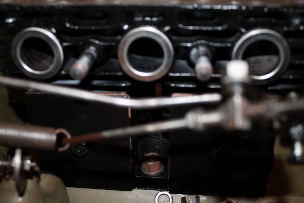
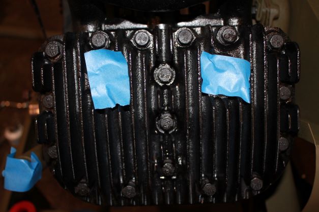
Gaskets were coated with copper high heat gasket sealer and the heads were installed with dry bolts and washers.

Lubrication
The oil line from the galley to the governor is installed.
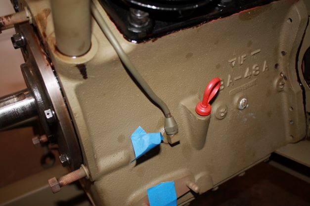
Cylinder Cooling Shrouds
While I was installing the cylinder shrouds I realized my engine was installed backwards, so I turned it around. I also installed the cylinder cooling shrouds leaving everything loose so I could mesh the many parts of the puzzle together.
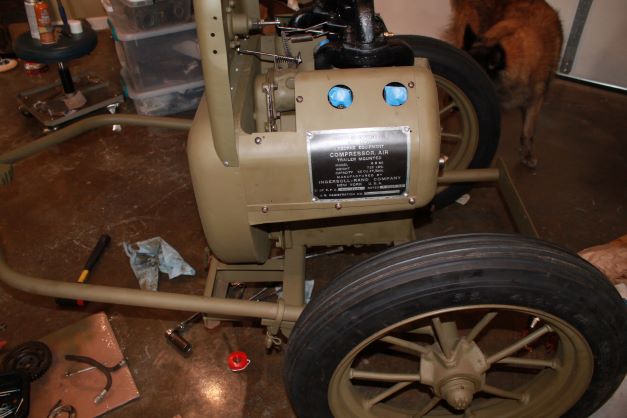
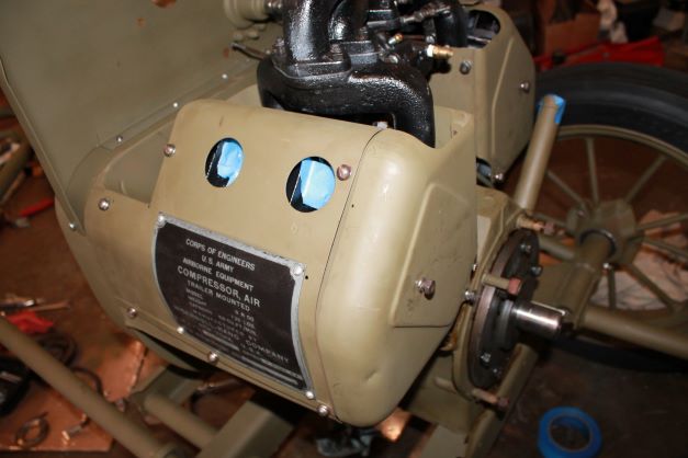
Engine Stop Control
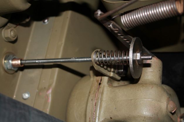
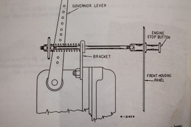
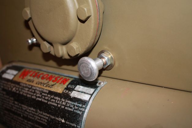
Today I manufactured the Engine Stop Hand Control. The only parts I had were the large washer, the nuts and the spring. I useda 5/32 metal rod and threaded the ends. I had to make it a bit longer than the original because I cannot find a replacement for the sleve that passes through the firewall. Everything today is cable and sleeve. I used a piece of bronze bushing and threaded it for two jam nuts to clamp onto the firewayy. The rod passes through that. I purchased two aluminum vintage tractor knobs and will use that on the throttle cable also.
Engine Muffler
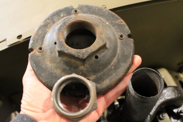
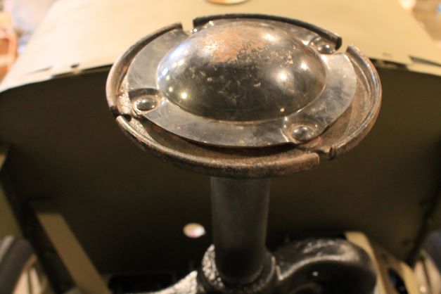
The TM calls for a muffler, WD27A. I could not find one anywhere. I did find a vintage WD48 listed on ebay. The problem is that the threads on the exhaust pipe are smaller than those on the muffler. No problem get a pipe bushing. I measured the threads on t he pipe at 1.5" and the muffler 1.75". FOr the last several months I could not find such a bushing. A plumber informed me that pipes are measured on the inside not at the threads, so I need a 1.25 - 1.5 bushing which I now have and voila!
Wisconsin Engine Filter
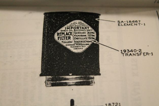
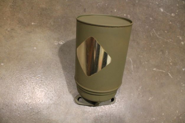
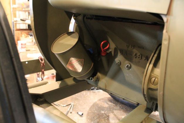
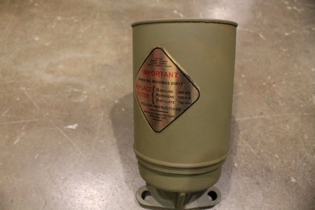
The engine filter for this engine is made by Michiana Filter COmpany. I could only find a vintage unpainted period replacement. The TM has a blury image of the decal that is on the canister. I made a facsimile using water transfer decals and added it to the canister after painting it OD.
Oil Pressure Gauge
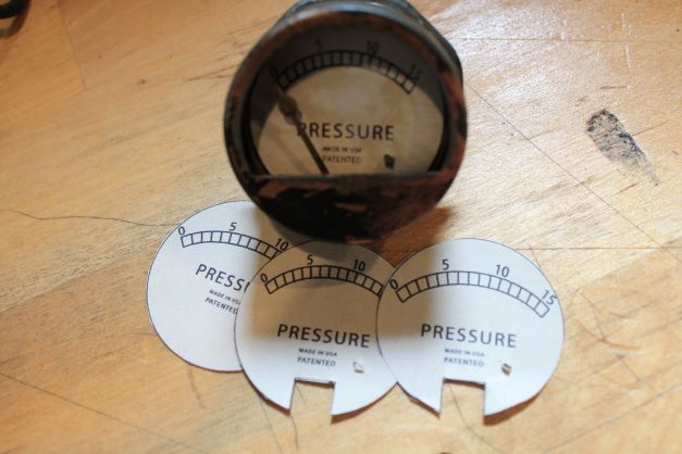
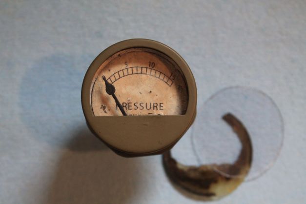
Working on the oil pressure gauge decal. I had to make several to get the scale correct and to have the needle align at the 0 mark. I added a bit or discoloration to the face to give it an aged look to hopefully match the other one which had a worn but useable face. I had to fashion a protective cover using thin plexiglass like the original gauge. I does not look NOS, but matches the air pressure gauge in patina.
Place Holder
Place holder