GPW 14518 Engine Rebuild
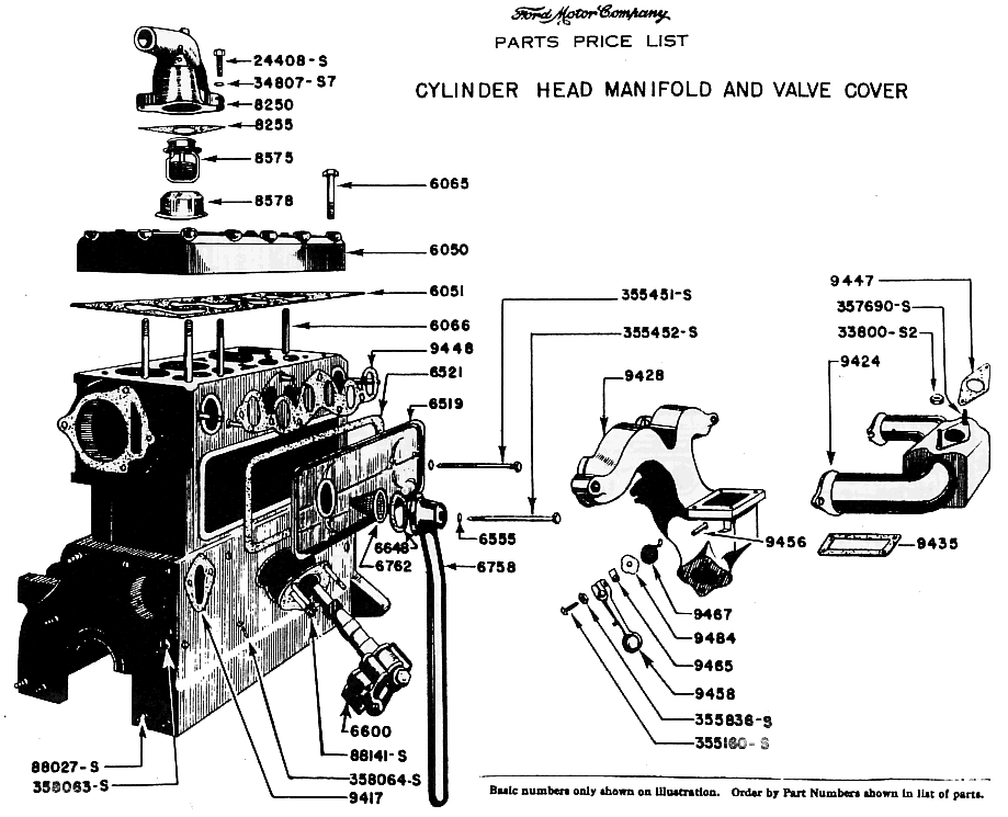
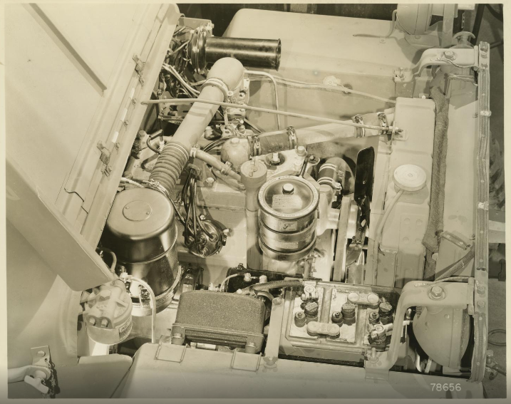
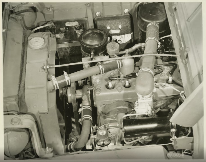
General Discussion
Finding a GPW that is all matching (Frame, data plates and engine) is increasingly more difficult. During the war, the wear and tear on engines resulted in quite a few replacement engines being fitted. THis was done in the field, at the ordnance company vehicle repair facilities behind the front lines and at different echelons, and at the major depot repair facilities in the US. After the war, there were several refurbishment centers in Europe who did major GPW and MB repair and refirbishment also.
Many jeeps were purches by farmers, mechanics and enthusiasts after the war ended, and these too say their fair share of engine overhauls and replacements. It is not uncommon to find an early GPW with a post-war CJ engine installed, or even the beefier T-90 transmission.
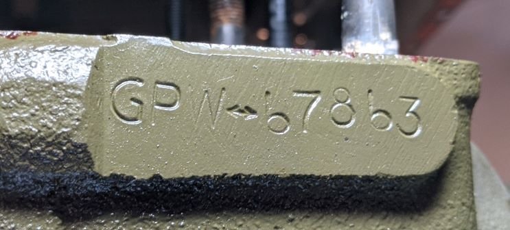
I find myself with an April 1942 frame 14518 and a GPW replacement engine GPW 67863 from approximately 12 October 1942. The difference is in itself not problematic, as it is common to find an unmolested GPW with a replacement GPW engine of unmatching serial number.
My problem is that the mismatched engeine has been rebuilt and I have some concerns. The three primary concerns which were uncovered during the exterior inspection and after dropping the oil pan are as follows:
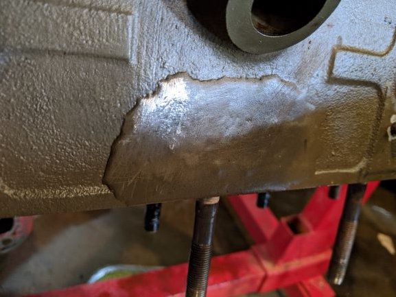
- The engine block was cracked just above the distributor. The repair appears to have been professionally done, but without being able to speak with the technician, it is hard to know for sure. It appeart to have been brazed and not welded. That is a good sign.
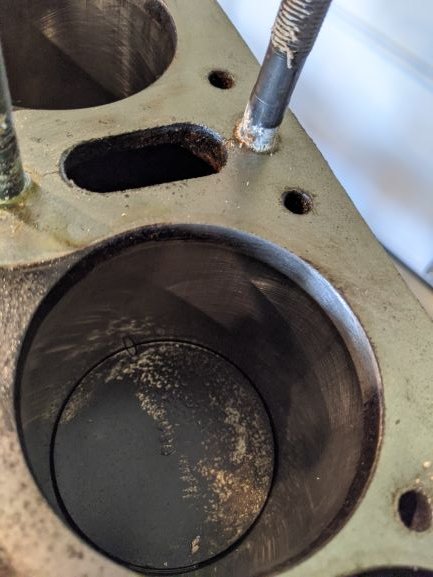
- The engine was bored to 0.080" over standard size, or 80 over. Normall 60 over is the limit that most rebuilders are comfortable with so as not to bore the walls near the water jacket too thin. I will have to have the 4 cylinders resleeved and will bring them to standard bore.
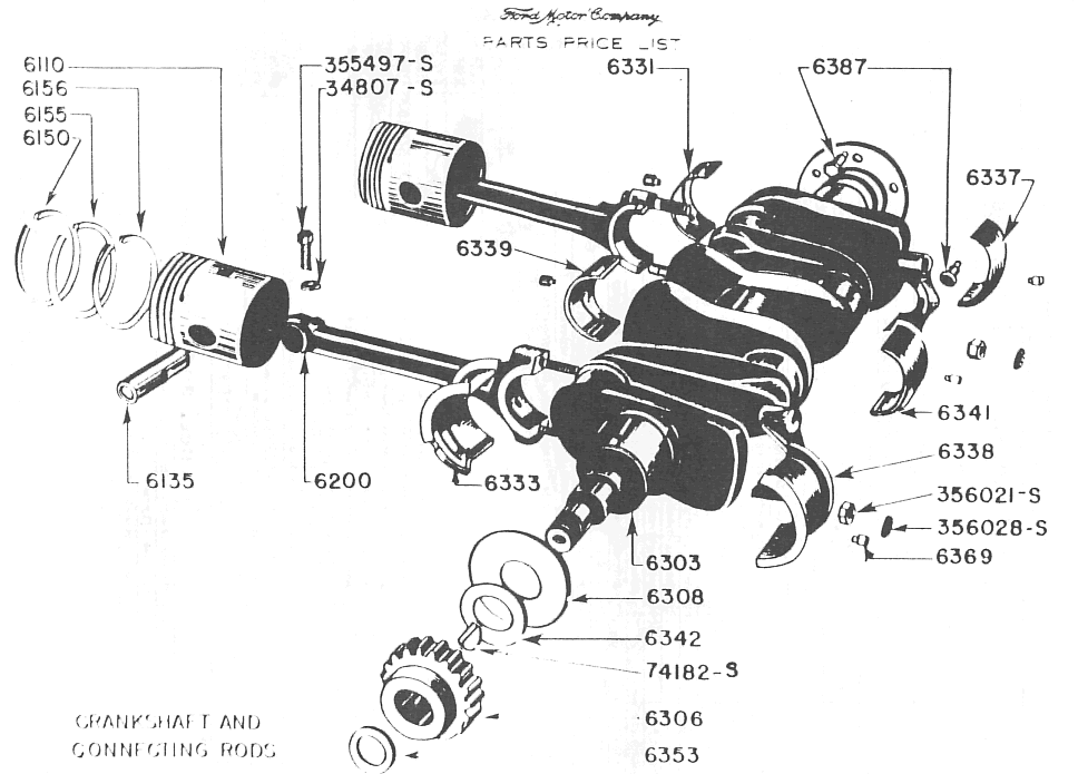
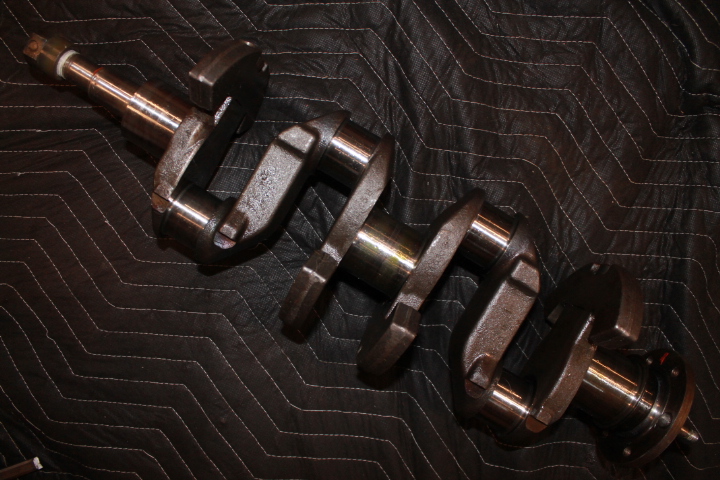
- The crankshaft does not appear to be an original GPW crank. I will know more once I get the engine taken apart further.
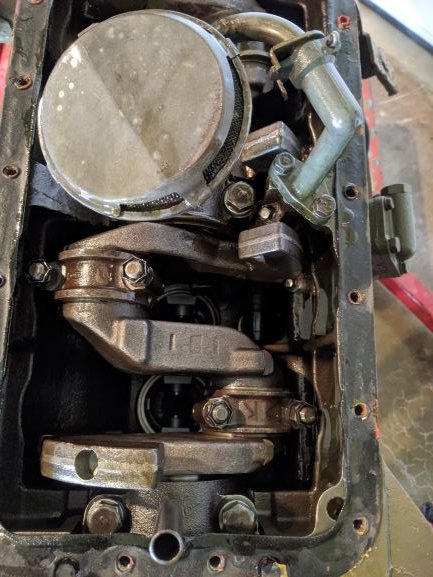
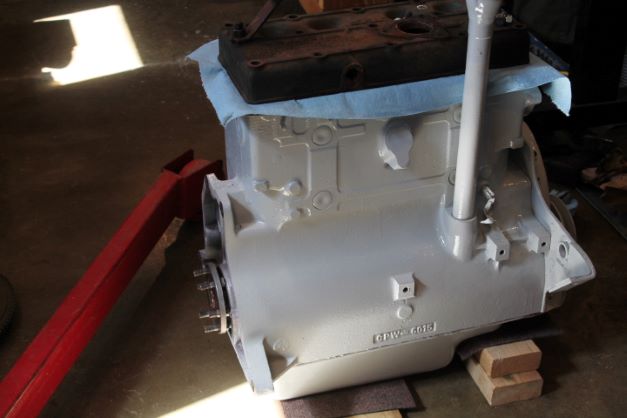
For now, here are some images of the engine as it now sits in my workshop. I will focus on the frame and drive train, saving the engine work for later.
TM9-1803A Disassembly
I have about 3-4 weeks of work to do on the frame and drive train before I could concentrate on the engine. In my last restoration I waited until I needed the engine before I sent it to the machinist.
This time I am taking a few days to strip the engine, bag and tag everything and take what is required to the machinist. Hopefully the engine will be ready when I have finished the rest of the work on the frame. At least I hope I am not waiting 3 weeks for parts.
TM 9-1803A states:
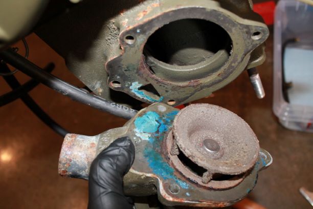
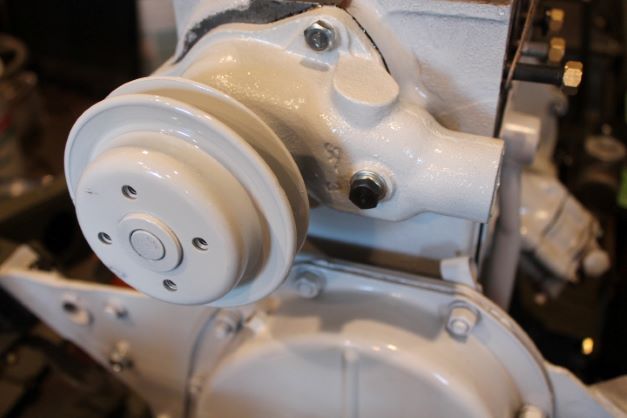
a. Remove Water Pump. Remove the four cap screws and lock washers that hold the water pump to the cylinder block and remove the water pump. DONE, image at right
b. Remove Intake and Exhaust Manifold. Remove the ventilating tube that connects the intake manifold and valve chamber cover. Remove the seven nuts and lift the intake and exhaust manifold off the engine. Previously accomplished.
c. Remove Water Outlet Elbow. Remove the three nuts that hold the water outlet elbow to the cylinder head and remove the outlet elbow and thermostat. Remove the thermostat retainer and thermostat. Previously accomplished.
d. Remove Clutch Disk. Loosen the six pressure Plate bracket cap screws in sequence a little at a time to prevent distortion of the pressure pate bracket. Remove the six cap screws, pressure plate and clutch disk. Previously accomplished.
e. Remove Flywheel. Remove the six nuts and lockwashers that hold the flywheel to the crankshaft. Tap the flywheel off the crankshaft with a brass hammer. Lift the rear engine plate from the engine. Previously accomplished.
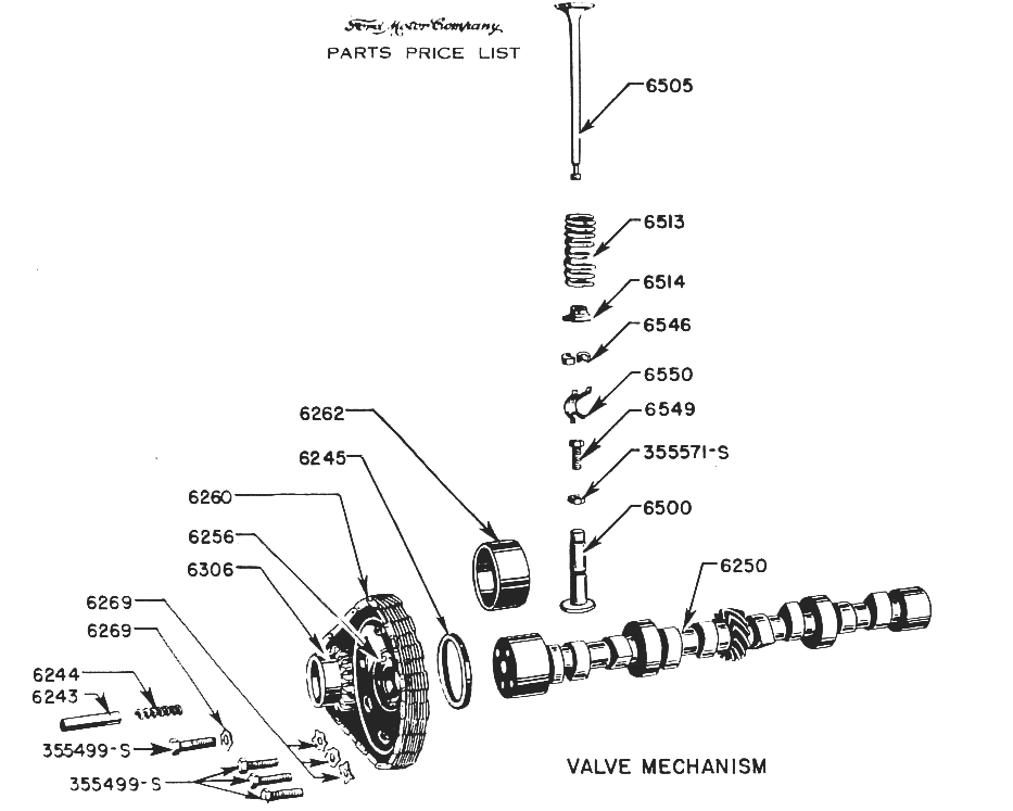
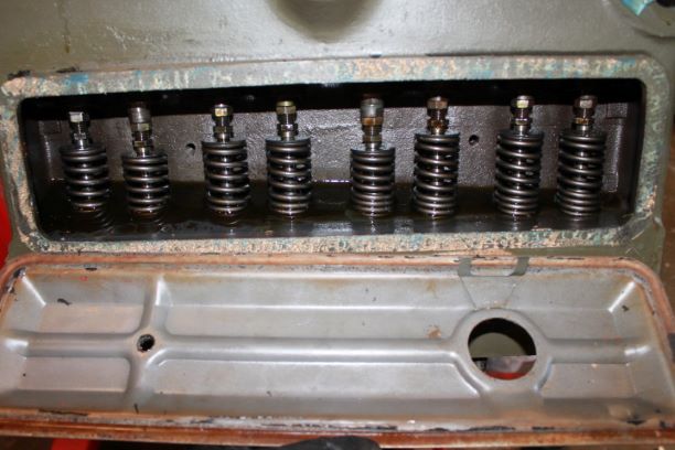
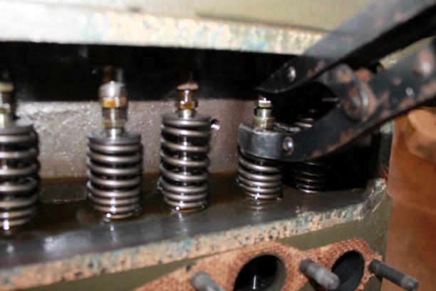
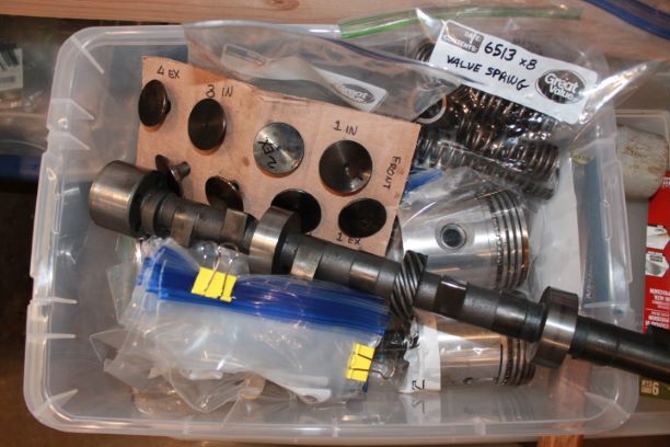
g. Remove Valves and Springs. Remove the two cap screws and crankcase ventilator assembly from the valve chamber cover and remove the cover. With a valve lifter inserted between the valve tappet and the valve spring retainer, raise the valve springs that are in closed position and remove the valve spring and retainer locks. Turn the crankshaft until those valves which are open become closed and remove the rest of the valve spring retainer locks. Remove the valves and place them in a valve carrying board so that they can be identified as to which cylinder they were removed from. Compress the valve springs with the lifter on each valve that is in the closed position and pull the spring off the guide. Turn the crankshaft until the tappets are in a closed position and remove the rest of the valve springs. DONE, image at right
TM9-1803A Disassembly, Continued
h. Remove Oil Pan and Oil Intake Float. Turn the engine on its side and remove the cap screws that secure the oil pan and fan pully guard to the cylinder block. Remove the fan pulley guard and oil pan. Remove the two cap screws from the oil intake float and remove the oil intake float. Done
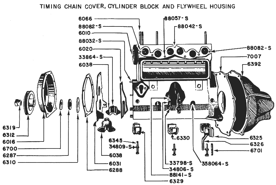
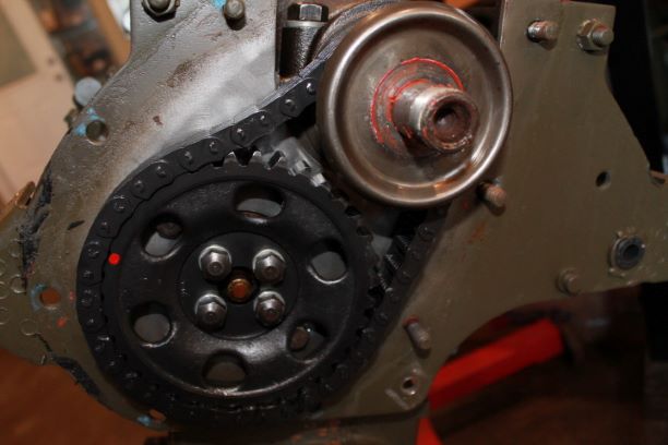
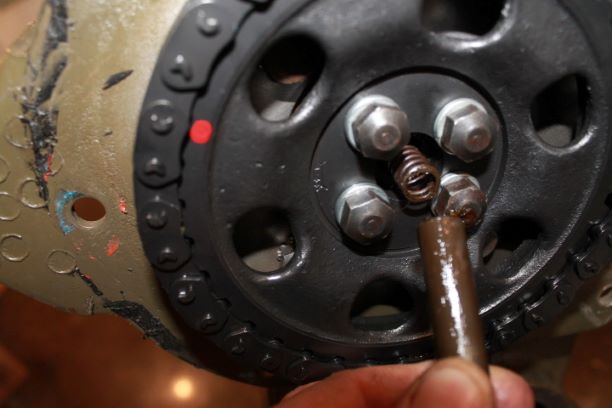
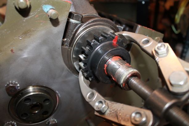
i. Remove Camshaft Sprocket and Camshaft. Remove the eight nuts and bolts that secure the engine front cover and engine front plate to the cylinder block and remove the cover. Remove the camshaft thrust plunger and spring. Straighten the tabs on the four camshaft sprocket cover screw lock washers and remove the four cap screws and lock washers. Lift the camshaft sprocket and the camshaft drive link chain off the camshaft. Remove the camshaft thrust washers. Lay the cylinder block on its side. Pull all the valve tappets toward the top of the cylinder block. Pull the camshaft out of the cylinder block and remove the valve tappets. Remove the three cap screws that hold the engine front plate to the cylinder block and remove the plate. Done, Photo at Right
j. Remove Piston and Connecting Rod Assemblies. Remove the two pal nuts, connecting rod nuts and connecting rod bearing cap from each connecting rod. Remove all carbon from the top of the cylinder walls. Tap the conecting rod and piston assemblies out of the cylinder block with the handle end of a hammer. Install connecting rod bearing caps on the rods in the same position as originally installed to prevent later improper mating of parts. Done,
k. Remove Crankshaft. Remove the two cap screws from each main bearing cap and remove the three main bearing caps. Lift the Crankshaft from the cylinder block. Done,
Engine at the Machine Shop
I have a few weeks worth of work to do before I am ready to tackle the engine. I took the engine, crankshaft, cam, pistons, lifeters and valves to the machine shop for an inspection.
They concluded that the vlaves, tappets, camshaft and crankshaft appear to be recently machined and show no wear whatsoever. Having miked the camshaft I found them all to be well above the wear tolerances listed in the TM. I agreed with their assessment of little to no wear, and this confirms that the engine was rebuilt (I have documentation from the rebuilder) and the the GPW was parked in a Ford showroom for nearly two decades
The machinist agreed that it would be better to re-sleeve the cylinders back to standard rather than chance running it for a few years hoping for no problems. This way it will afford several rebuilds before needing a re-sleve again. The machine shop folks will tank and bead blast the engine, remove the studs, clean the oil galleys and install the sleeves. They will check the valve seats and dress them as required. When I get it back it will be bear metal ready for some Ford grey paint, not the current OD.
On another note, and you can see this in the image with the timing chain above, the chain has stretched to the point where it sags noticable. I posted a small video of the movement.
According to my research, to leave this chain on the engine will result in timing chain noise or rattle, and premature failure well before the engine needs an overhaul.
Most of the GPW rebuilders are recommending to go with a "Richard Saunders Roller Unit" which includes both gears and the chain. Everyone recommends chainging out the gears with the chain as the gears will develop grooves from the wear of the chain.
The kit costs $225, but I am not wanting to redo the engine in a few years so I am going to change the thre parts out now while the engine is out and I have the time.
Inspection
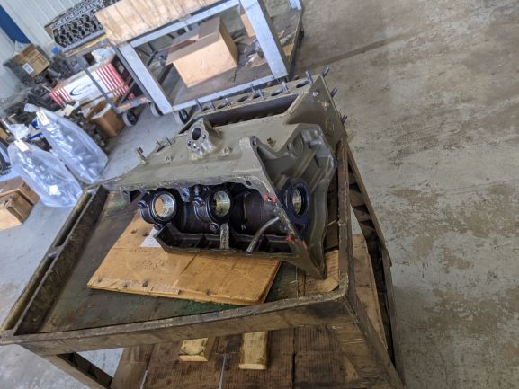
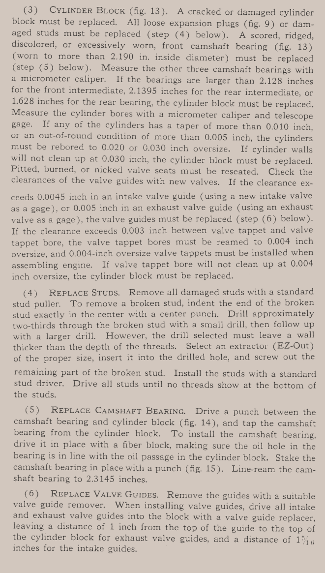
The cylinder block was taken to the machine shop. It was cleaned, magna-fluxed and inspected by the engine specialist. They replaced the rear camshaft bearing, removed all of the studs and sleeved the cylinders, re-boring them to STD, which is 3.125"
The diameters of the camshaft bearings from front to rear are as follows:
Front: 2.178" Should be 2.1870" to 2.1890"
Front Inter: 2.122" Should be 2.125" to 2.126"
Rear Inter: 2.066: (TM Wrong, should be 2.0625" to 2.0635")
Rear:1 622" Should be 1.625" to 1.626"
The diameters of the camshaft journals from front to rear are as follows:
Front: 2.180" Should be 2.1860" to 2.1855"
Front Inter: 2.123" Should be 2.1225" to 2.1215"
Rear Inter: 2.060" (TM is wrong should read 2.0625-2.0635")
Rear: 1.625" Should be 1.6230" to 1.6225"
The difference between the actual journal and bearings for oil passage are as follows:
Front: 0.002", Front Inter: 0.001", Rear Inter: 0.006", Rear: 0.003"
Since acceptable bearing clearance standard for most vehicle applications is 0.001-inch of clearance for every one inch of crank journal diameter, then the following applies, rounded to the nearest 0.0005"
Front: 0.0020", Front Inter: 0.0020", Rear Inter: 0.0020", Rear: 0.0015
The cylinders were measured top, middle and bottom, longitudinally and laterally all being 3.215, +/- 0.0005"
The valve guides and valves are all new with no wear, hardly any carbon and no side to side movement of the valves when inserted in the guides.
All cylinder head and manifolds studs are removed and will be replaced with new studs and since this is an early 1942, I will use the 9 hex head bolts with the studs also. I understand the concerns with reseating the bolts vs the studs, but am going to give it a shot.
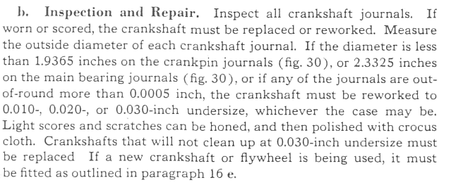
The journals on the crankshaft measured as follows:
Mains: 2.304" 0.030" under
Rods: 1.917": 0.020" under
Oil Pump Rebuild
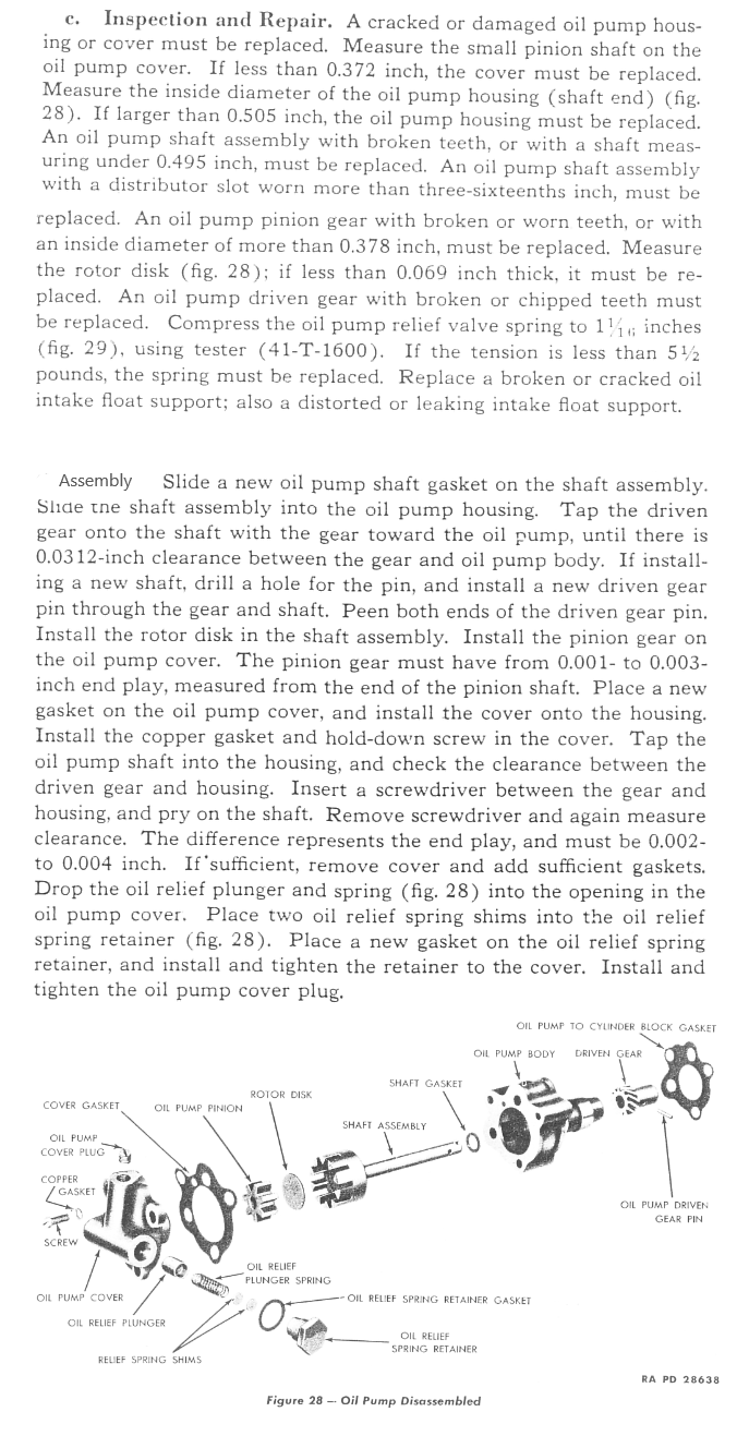
Not as easy as I expected, but it was a fun challenge. The KEY is to inspect the parts for wear (ALL OF THEM) I would urge you to go to the G503 and find the original Ford drafting images of all of the oil pump parts and scope every piece.
https://forums.g503.com/viewtopic.php?f=4&t=292445&sid=9f08615793b78e7807db1a959e38ed41
The take off parts that I measured were the cover, the body and the Rotor Disk. Measure every possible surface that might have wear and compare it to the Ford blue prints. I suspect 1-2 thou is fine and if you are within the tolerances on the drawings, your part is probably hardly worn.
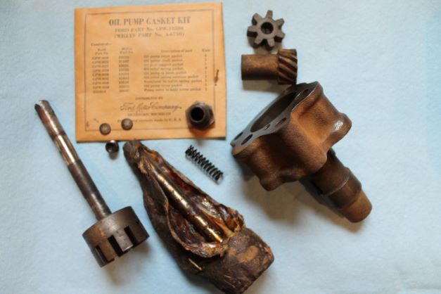
I had 3 NOS rebuild kits which have the shaft assembly, the pinion, the driven gear and the pin that holds the driven gear to the shaft. I also had a NOS gasket set. The cork shaft washer is dry so I made my own with my punch set.
Out of the 3 NOS kits I had problems with two shafts. Despite being in cosmolene, one was corroded, and the other would not turn on the cover as it was not machined properly. It took me a while to overcome these setbacks.
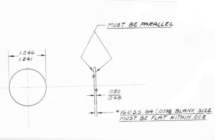
Also the TM lists the thickness of the disk as 0.069:. That is wrong. The Ford drawings show 0.048-0.050" Mine was right at 0.049"
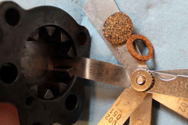
Taking the old shaft off was troubling as it was nearly rusted to the gear. Eventually I ended up with a good cover, body, shaft, driven gear and pinion. I used a feeler gauge to check the clearance between the rotor and the inner body. I am at 0.015". The bigger the gap here, the less oil pressure you will have. Another important measurement is the top of the rotor to the cover. Another TM allows 0.001-3" That is adjusted with the gaskets. Follow the procedures in the TM. I needed 1 gasket to achieve free movement with less than 0.003" clearance.
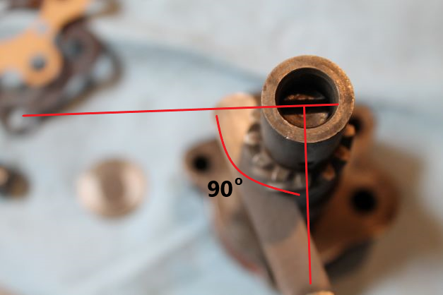
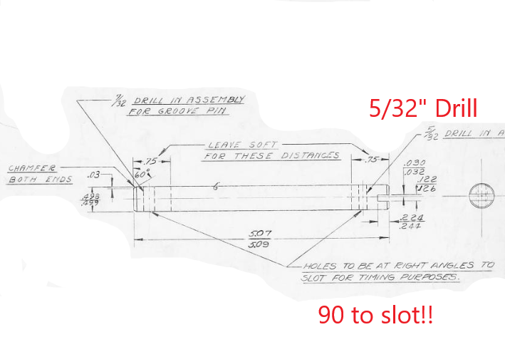
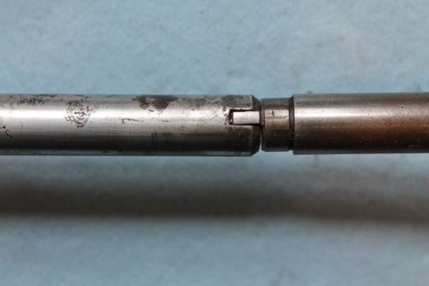
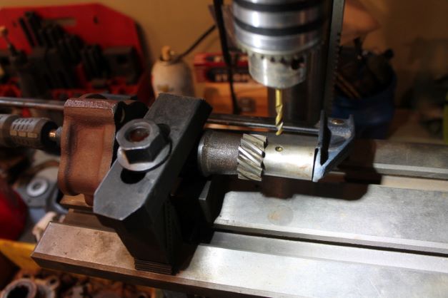
Ensure you align the shaft and gear as shown in the picture below. The drilling dimple on the driven gear should be 90 degrees offset from the slot in the end of the shaft. These align with the distributor shaft key to create proper timing. That is not in the TM either.
Drilling the hole IMHO is not possible with a hand drill. I used a Rube Goldberg combination of things to get it set up on the drill press. I did not want to use too much pressure on the body or shaft and bend or crack anything. Also the gear wants to spin on the shaft so you have to isolate it as well. I am not sure how critical the 90 degrees is, but i supsect one has to get the right tooth in the cam gears so that timing is in the ball park. From there you can probably make minor adjustments to timing by rotating the dizzy a bit.
In the end I have a properly rebuilt oil pump with minimum clearances and I am hopeful this will produce good pressure. If it does not on the first start up I may resort to the $160 Melling pump.
Connecting Rod and Piston Assembly
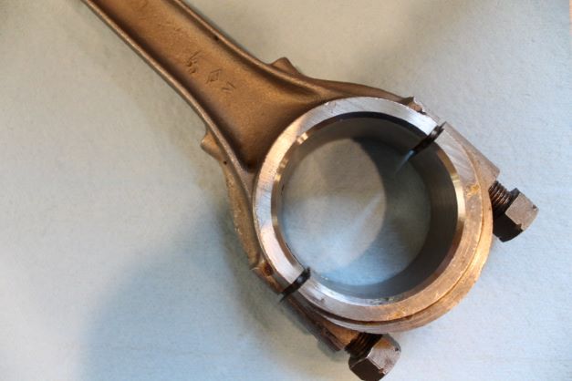
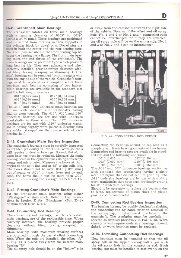
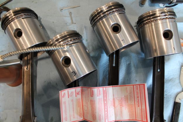
I am starting with new pistons and rings. The connecting rods are all in excellent shape as well. I did notice that I have 3 rods designed for the 1st and 3rd cylinders and only 1 rod for the 2nd and 4th cylinder. When the incorrect rod is installed in the wrong cylinder, you either have the oil squirt hole facing the wrong way, or the end of the rod that is on the wrist pin will not be aligned in the center of the piston, thus putting a slight side load on the piston as it is pushed up into the cylinder. Thankfully I had an NOS 2/4 connecting rod to swap out with the 1/3 rod.
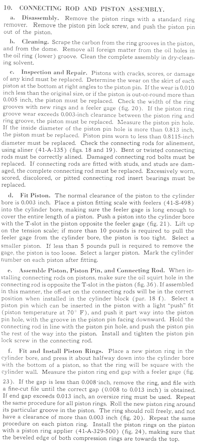
I checked the fit of each piston in a cylinder using a 0,003 wide feeler gauge. I could not quite get 6lbs on the pull gauge. It was slightly on the loose side. The thickest gauge I could slip between the piston and cylinder was 0.004". the 5 would not go. There is no way that an oversize piston would do so I feel confident that this is a good fit.
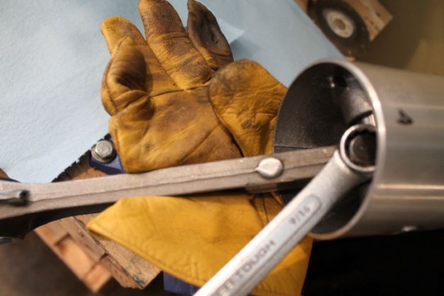
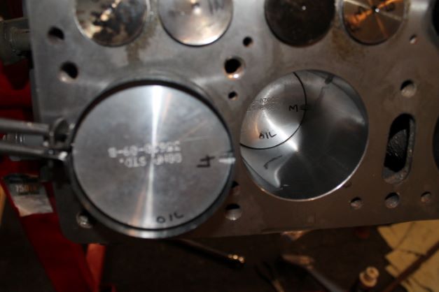
I installed a piston on each rod making sure to orient the oil squirt hole in the correct manner as outlined in the TM. NOTE: The TM image, Fig. 39 is INCORRECT. This has been document at length on every site. Use the enclosed image for orienting the 4 connecting rods and pistons correctly. I tightened the wrist pin bolt by clamping it in a vice with leather to prevent damaging the rod, and keeping the bolt close to the clamping point so as not to bend the rod as I torqued the bolt.
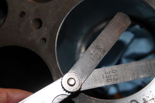
Using the 0.008" feeler gauge as a GO-GAUGE and the 0.013" gauge as a NO-GO GAUGE, I checked all 16 rings. Note the narrative lists 0.0013" as max and the table well below lists 0.0015" I will need to confirm with the post war manual. I found a few of my rings right at 0.0015" so I am calling it good.
For the installation of the oil rings, the TM is not helpful as ring design has changed. Follow the instructions that come with your rings. Do not forget to index the gaps as outlined. (not shown in image)
Engine Assembly
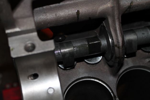
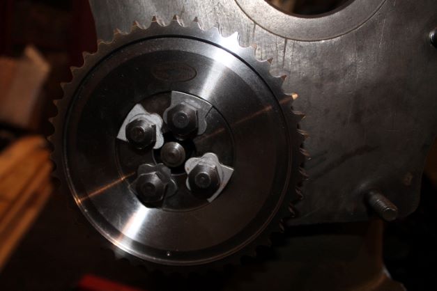
I gave the engine one more good cleaning with air and pipe brushes and a long reach magnet just to make sure nothing was left inside. To install the tappets and cam I spun the engine upside down and installed each respective tappet in its guide. I used liberal amounts of assembly lube on the tappet neck, the head and the cam bearings. The cam journals was lubed as well, then slid into place. I installed the camshaft thrust plunger spring, bolts and lock washers with new sprocket. Everything is only on finger tight for now and I will bend the tabs down when I do the final adjustment.
There are some adjustments to make with the alignment of the cam. I'll do that following the instruction sheet for the new sprocket and chain set later.
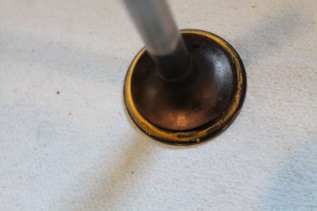
I put each valve in its respective guide and checked the seal using yellow gear paint. Each showed that there was suitable contact between the beveled edge of the valve and the valve seat. A better way to check this is to pull a vacuum on the port with the valve seated. You should read 20 lbs of vacuum. I do not have that set up.
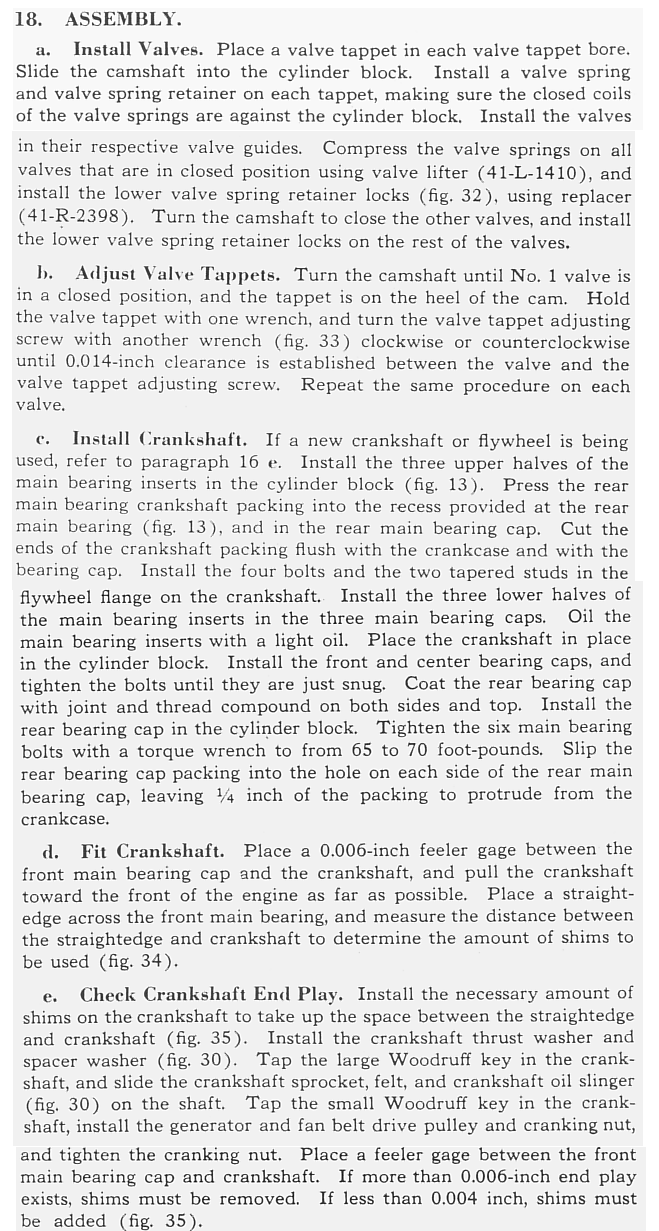
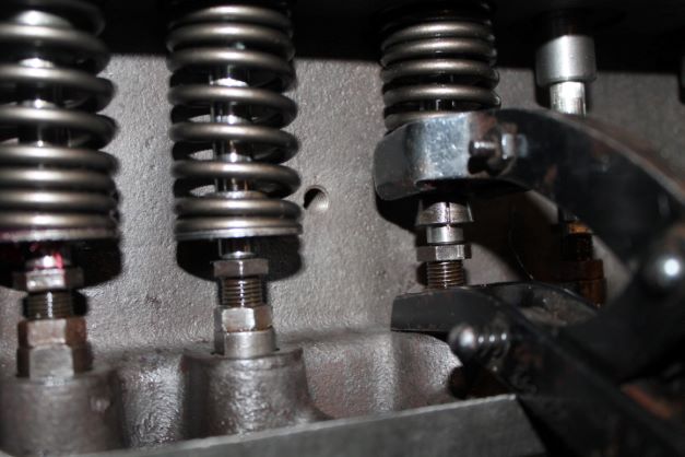
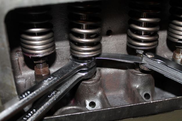
I installed the valve springs, the seat and the keepers and then ensured I had 0.014" clearance between the valve end and the tappet. A few minor adjustments were needed.
Crankshaft Installation
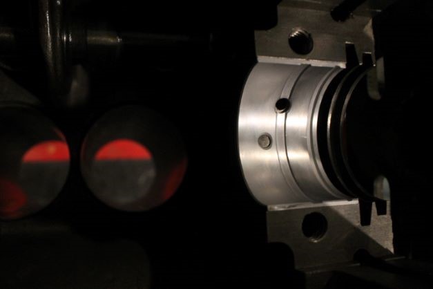
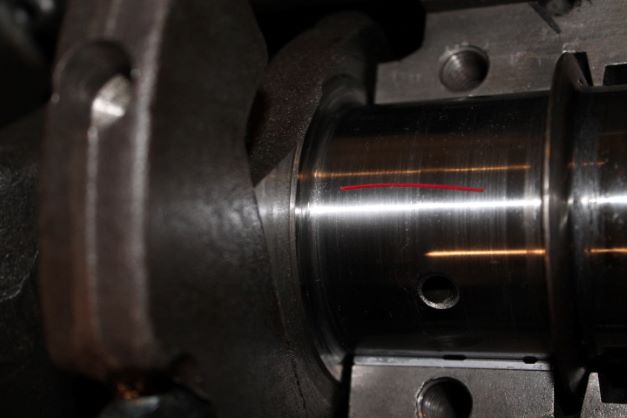
I am following the TM installation for the crankshaft with the exception that I will install it dry using plasti-gauge to verify the clearance between the bearings and the journals. Without doing so I cannot confirm the work of the previous machinist in setting the proper oil clearance of the bearings. I won't install the RMS unitl after this step is done.
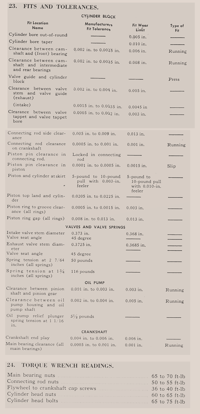
For reference I am posting the fits and tolerances for engine rebuilding as annotated in the TM 9-1803A.
I received my new 0.030" over-sized bearings and cleaned them up with electro-cleaner to remove the shipping preservative and any grease. I layed out the bearings and matched them with each of the caps making sure the oil holes, grooves and pin poles lined up properly. I cleaned teh bolts and lightly snigged everything down just to check.
I put a light coating of oil on each bearing, then cleaned the crank again and laid it into the upper bearings. I rotated it a few times just to check that everything on top was seated properly and nothing was binding.
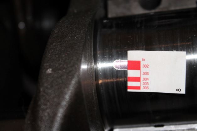
I placed a length of plasti-gauge on the top of each crank journal and installed the lower caps snugging the bolts down by hand and tapping the cap screws with a rubber mallet. The bolts were torqued down in sequence to 40 ft/lbs, then 60, then the specified 65-70. I used 67.5 on the wrench to meet in the middle.
I spun the crank often between torquings to make sure nothing was binding. It was not. I then removed the caps and checked the plasti-gauge against the paper gauge provided with the material.
The specifications in the TM are changed elsewhere. According to the Jeep Manual (post war) and Federal Mogul) these numbers are acceptable specifications for Oil Clearance
Federal Mogul
RODS, 0.0005-0.0025"
MAINS, 0.0008-0.0029"
JEEP Factory Specifications.
RODS, 0.001"-0.0019"
MAINS 0.0003-0.0029"
My readings appear to be about 0.0016-18" on all three journals. It could be tighter, but this should provide a reasonable wear life under mormal collector driving conditions provided the oil is kept clean, changed as required, and the engine temperature is kept within normal range.
Crankshaft End Play and Sprocket Alignment
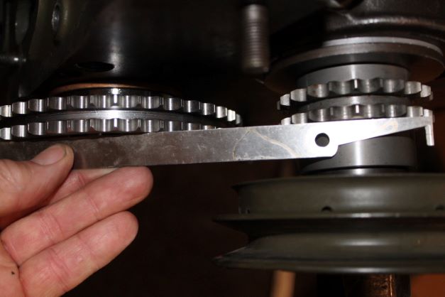
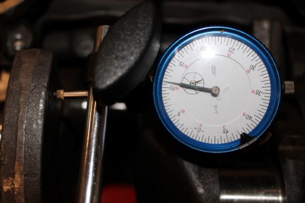
Before I finish up the install on the crank I need to measure end play and see how the sprocket and cam shaft gears line up. If they are not in the same plain, the chain could bind causing excess wear and early failure. If the end play is excessive, the crank will move too far forward when the clutch is applied and this will move the connecting rods forward on the wrist pins, changing the dynamics of the piston movement/ wear in the cylinder and elsewhere. The TM requires end play to be between 0.004-6". That is measured by installing the thrust washer, the spacer, the sprocket and the pulley and tightening everything down with the nut.
If everything is done correctly, then the two gears will be on the same plain and the small end play will not cause excessive binding on the chain.
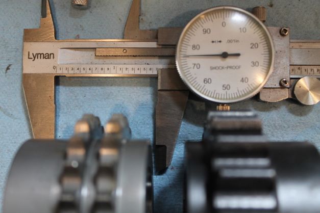
The image shows the old sprocket and the new one. The new one is manufactured 0.010" longer eliminating the need for the spacer. As you see in the image, the faces of the sprocket and cam shaft gear allign nicely.
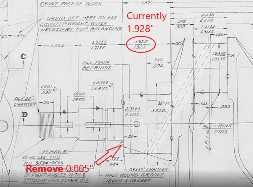
In my case I have 0.0011" of end play. I don't want to explain why that is (take a few pages), but since I have no shims to remove to correct end play, I will have to have the machinist remove 5 thou from the front surface of the crank that contacts the thrust washer. The current length of that section is 1.928" which is 0.003 longer than the max allowed and 0.005 longer than the minimum. If I shave 0.005 from that section I will still be within the original dimension. Following the removal of 0.005" the end play was reduced to 0.0075" I will accept that.
Rear Main Seal Installation
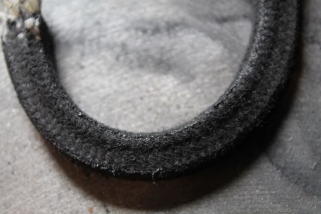
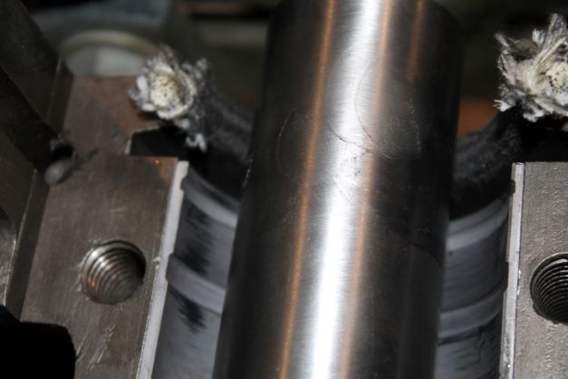
There is a lot of controversy surrounding RMSs on the L-134 engeine as of summer 2021. The neoprene seals were billed as easy to install, and they are. Some folks had succes, some had massive leaks and others found the seals heated up the crank and burned out and leaked, possibly damagind the journal. The causes were mainly faulty seal design (too loose or too tight) and rebuilders not realizing (manufacturers also) that the RMS journal on the crank is not the same as the main bearing journals. The current manufacturer, Best Gasket) is looking into this perhaps, and many rebuidlers are welding up the RMS journal and grinding it to fit a seal. The simple solution is to use a rope seal and learn how to do it properly. I found Metalshaper's video on installing a problem free RMS rope seal and I am using his technique in my engine as who knows when the seals company will get it right. Start the vid at 2:55.
According to many sources, the Graphite RMS does not need to be soaked in oil. Only lube the surface that contacts the journal when doing the final burnishing. Also do not leave yourbearings in when burnishing as you can scratch them. Just follow the video as I am doing.
I turned the crank using the front nut until it seemed smooth and not "too difficult" to turn. I am guessing the moment was about 30-ish ft/lbs. I then follwed the instructions on the video for gasket sealant on the cap surface. Don't forget your flywheel bolts/dowells.
Heat Riser Replacement/Manifold Assembly
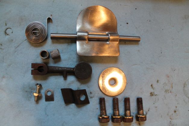
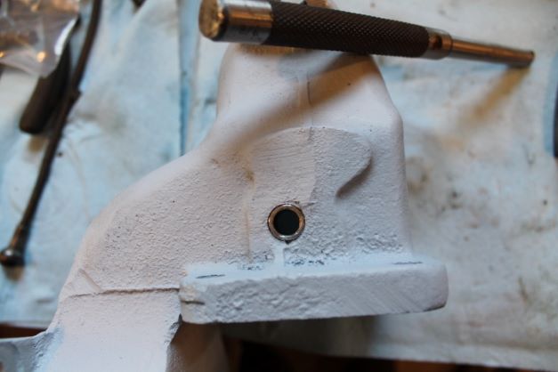
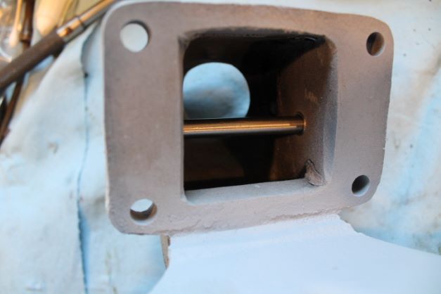
The intake and exhaust manifolds have been sand blasted and painted with VHT light grey. 3 coats IAW the instructions. I used a busing driver to install the two new bushings. You might need to use a round fine file to clean up the edges so that the shaft will not bind. Check that it inserts all the way through with the non-splined end and that it rotates freely. If it binds in any way, the riser will bind also. Get it correct at this step. NO BINDING!
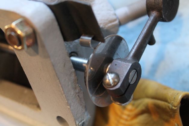
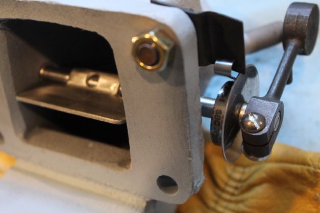
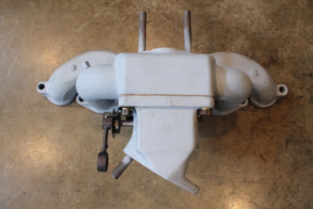
I then assembled the pieces IAW the TM in the configuration as shown here. The spring rest is held on with one of the bolts and a nut during the mock up. This is the orientation when cold, spring compressed and the flapper down. Mark the shaft and flapper for welding.
Weld carefully as you only get one shot. Too much heat and it may warp the shaft. Test your work with a heat gun to make sure the riser closes when hot.
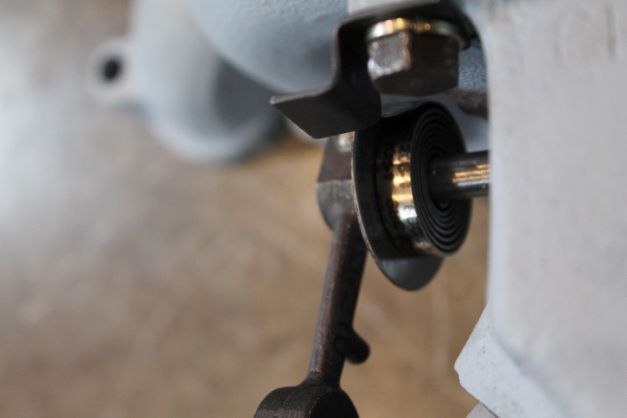
The two pictures below that show the spring are incorrect. USE THE LAST IMAGE for PROPER SPRING ORIENTATION! Take note of the difference. The spring contracts when heat is applied and this causes the shaft to rotate counterclockwise when viewed from the left side. THis raises the counter weight and closes the flap in the manifold.
Installing Connecting Rod and Piston Assemblies
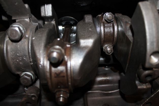
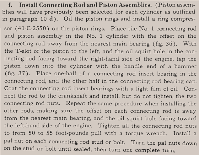
I made double sure each piston was pointing forward, that the oil squirt hole was on the right side of the engine and the "T" slot on the left. This sets the orientation of the rod offset correctly as discussed above. I applied assembly lube on each half of the bearings, slipped a piece of rubber hose on the full length of the bolt and liberally oiled the pistons and rings so that the entire cylinder walls would be covered with oil.
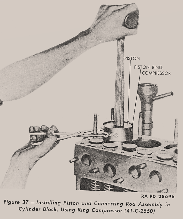
I slipped the No. 1 piston 3/4 of the way down in the front cylinder with the "front" notch to the front . I then used the ring compressor and a rubber handle to tap the piston through the compressor unitl the top ring was in the cylinder. Its best to orient the block upright so that the rod hangs over the journal. As you tap it down, the rubber hose protectors will help to guide the bolts over the journal. I then rotate the block 90 degrees and after lubing the cap, install it and the two bolts finger tight before moving to the next piston. I'll do all 4 before torquing to 52.5 ft/lbs and installing the NEW PAL nuts.
Further Assembly
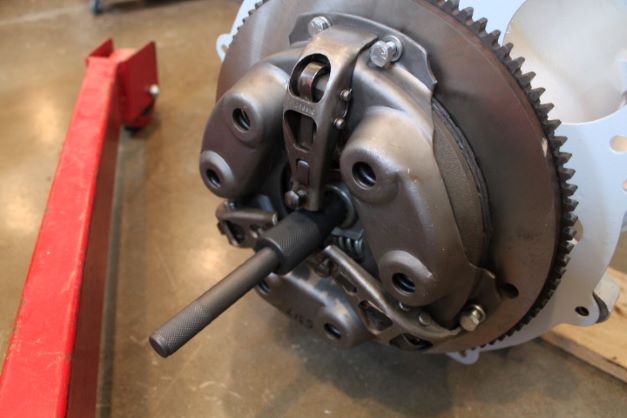
I'll install the clutch disk and flywheel after the oil pan is put on and I can get the engine off the stand.
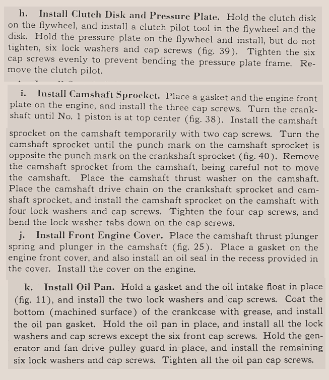
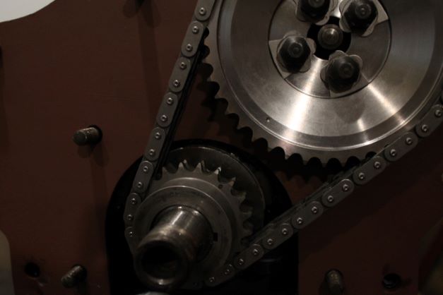
The key is to get the No. 1 cylinder at TDC and install the cam sprocket properly so that the timing marks are alligned as indicated in the TM. You will have to install the cam sprocket and rotate the cam independent of the crankshaft to get the marks to align. The cam sproket holes are not all drilled at 90 degree marks, so that the sprocket will only go on in one orientation. (Unless you only use 2 screws)This ensures when roated without the chain to align the marks, the valve and crank timing will be proper.
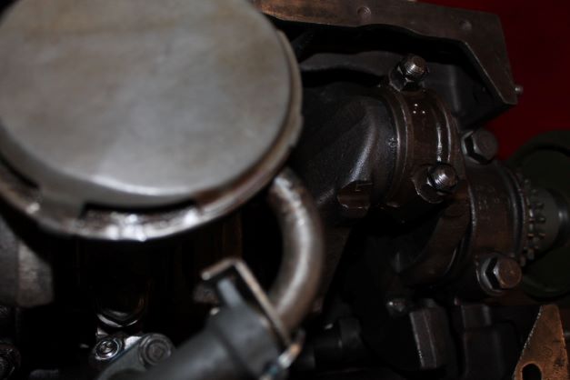
Many engines are rebuilt without the pulley splash guard which goes below the oil pan. If you do so, the bolts will exend deeper into the timing cover holes and might possibly dig into the cover. I am using a reproduction pullet guard.
One note to remember is to ensure that you remove paint in the areas of the front engine plate so that the bonding straps can transmit electricity through to the engine. The rest of the assembly is non-descript, simply following the TM.
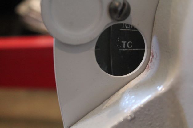
I left the engine at TDC so i could install the flywheel and clutch assembly.
Engine Installation
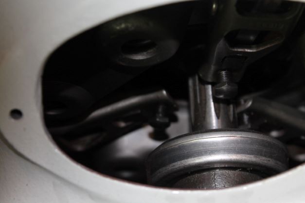
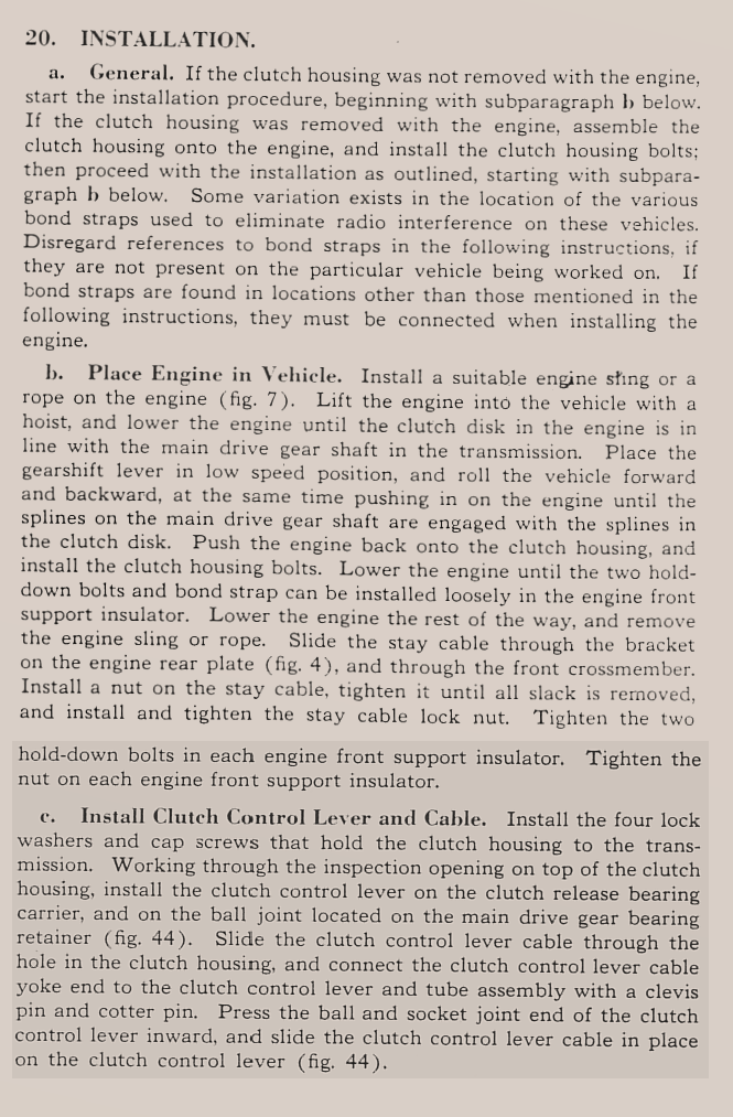
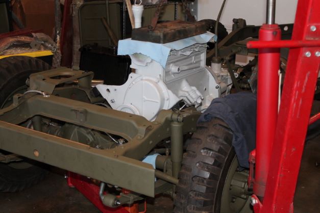
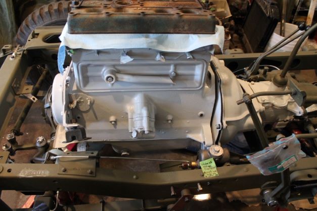
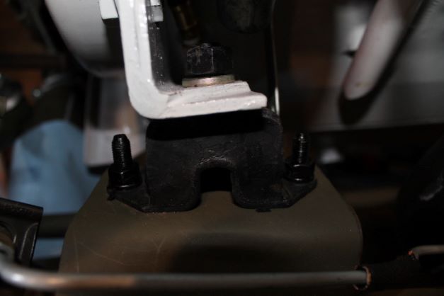
I elected to install the bare block with the clutch in the engine without all of the accessories as I figured it woud be lighter and easier to work on in the frame than on the ground. I used my engine hoist and it setted in nicely. I had to turn the crank sighty to allow the spines of the transmission input shaft to align with the clutch splines, and I had to do a bit of adusting of the right motor mount insulator to get it to seat properly. It works best to have the insulators attached to the engine mounting plate, just loosey and then before seating the engine fully on the mounting brackets of the frame, insert and tighty secure the two bolts that hold the foot of the insulator to the mounting bracket. This allows things to be slowly adusted as you lower the engine into place. In a perfect world everything would line up nicely, but since these mounts were added to the frame it just did not line up exactly.
Installation of Oil Pump, Manifold and Clyinder Head
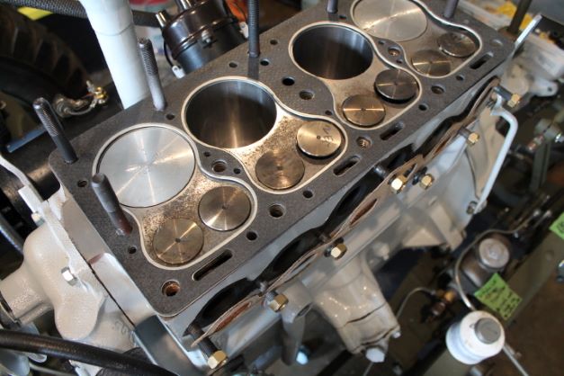
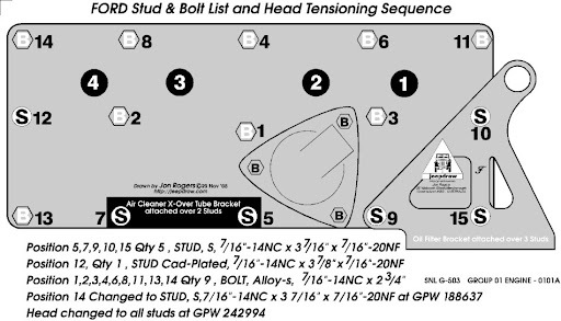
l. Install Cylinder Head. I am using the original style of securing the cylinder head which is 6 studs (5 regular length and one long one) and 9 cylinder head bolts. I will use thread sealat on each and torque them as per the diagram copied from the G503. I will step up to the torque starting at 40, then 60, then final torque of 60-65 ft/lbs for the nuts and 65-75 for the bolts IAW the TM.
I am using the Felpro 7285B which will work in either a CJ or a WW2 engine. The manufacturer installation directs the use of NO SEALANT, whcih is what I am doing.
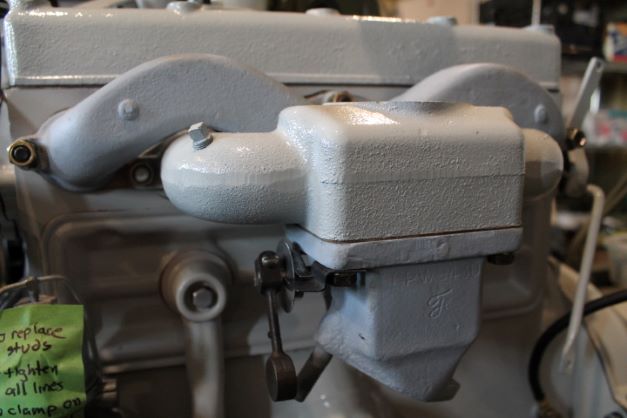
m. Install intake and Exhaust Manifold. It is critical that you use the proper studs and brass nuts along with the dished washers to install the manifold. The brass will prevent heat corrosion and seizing of the nuts to the studs. There is a controversy about the proper direction on how to face the dished washers that go on. The TM states: "Install manifold with new gaskets. Install manfold clamp washers with convex surface toward manfold. Install manfold nuts drawing them up tight."
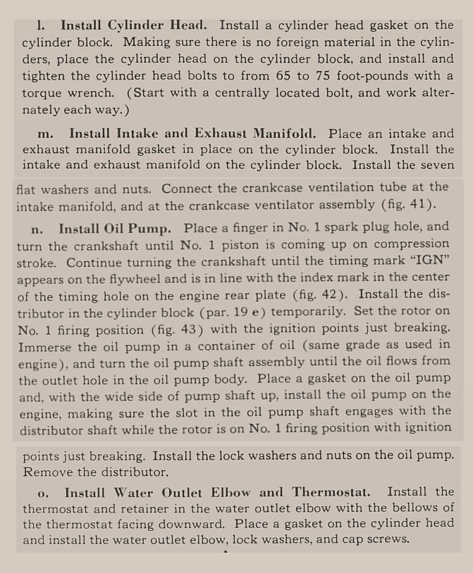
o. Install Water Outlet Elbow and Thermostat. It is reccommended in many places to drill a small hole in the thermostat housing to allow excess air to leach out of the engine. I did that and then inserted the thermostat into the top of the elbow with the spring pointing down and inserted the retaining sleeve. The sleeve sticks down slightly below the bottom flat surface of the elbow, I am thinking that will move upwards as torque is applied to the bolts and the upper "fingers" of the sleeve bend downward from the thermostat. I used aviation gasket sealer on the top surface of the block for the gasket as it was flat, but the surface of the elbow was pitted. I used red RTV there. I should get some water proof sealant next time.
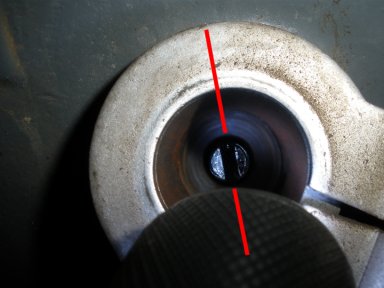
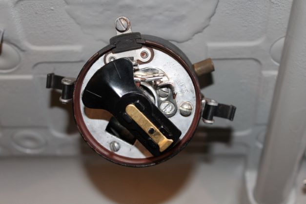
n. Install Oil Pump. Installing the OP is critical to timing of the engine as the distributor spline lines up with the oil pump. Great site listed below for procedures, the image is from them. Pay careful attention to the fat side of the oil pump shaft as that should be on the right side as you look down into the distributor hole with the slot oriented toward 11/5 o'clock-ish. The ultimate test is when you put the dizzy into the recess, its tab will only fit one way and if you've done it correctly the rotor will point to about 5 o'clock position.
http://legacy.1943gpw.com/c-35-G503_WWII_Jeep_Oil_Pump_Distributor_alignment.aspx
Installation of Accessories
a Install Water Pump. Not sure why it says 3 cap screws as there are 4. I used aviation gasket sealer and installed per the TM. the 4 bolts are torqued to 12-17 ft/lbs
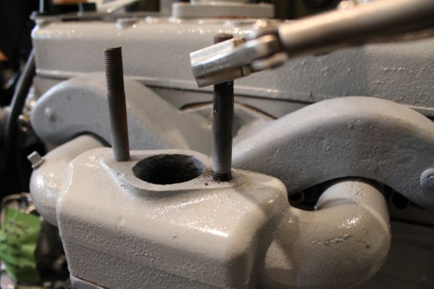
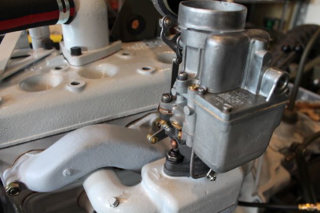
b. Install Carburetor. I did not realize the studs in the manifold were about 1" too long. THey impeded the installation of the carb. I used heat and PBB to remove them ind sourced some 1 1/2" 3/8-16 studs. I inserted the diffuser over the studs before securing the studs.
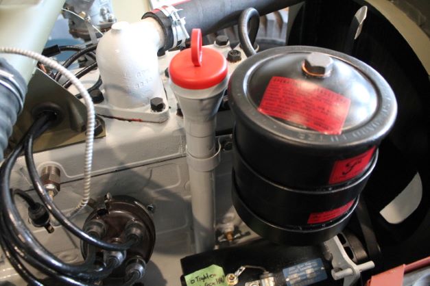
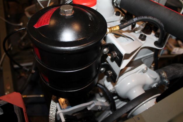
c. Install Oil Filter. The canister installed fairly easily. It was just a bit tricky getting teh oil tube clamp bolt started. Also ensure that you place the bacnds in an appropriate position so that the upper band is low enough to provide clearance for the oil return line to thread in. I used teflon tape on all fittings. Make sure to install the rubber seal in the lid and the copper washer under the bolt.

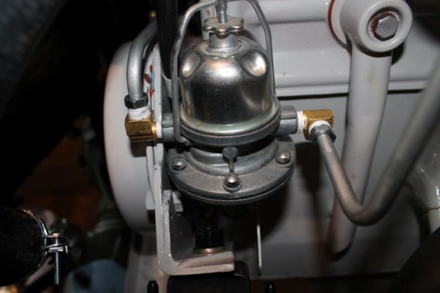
d. Install Fuel Pump. I elected to use studs on the pump to secure it. The TM calls for 2 ea 5/16-18 x 7/8" hex head screws. I will need to change that. I took the time to install the brass oil line to the filter and route the hose throgh the clip that is secured to the chain cover at the 1 o'clock position. The hose is routed behind the pump and there is not much room back there so it has to go in first.
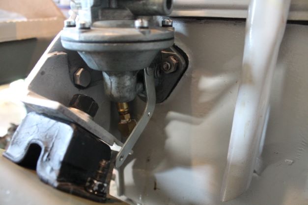
e. Install Distributor.4 The distributor installation is discussed above with the oil pump.
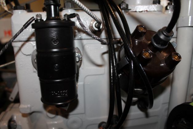
f. Install Ignition coil. The coil bracket, IGC was blasted, primed and painted.I used a RFJP Coil mounting hardware kit to secure it to the two studs. I also added the grounding strap. The coil is a modern 6v coil installed in the case of a Ford Model T metal coil canister that I took apart and used as a covering for the authentic look. Now I can replace the coil easily in the can. I simply used JB weld to install a No. 8 thread brad hole Tee nut. for the grounding strap.
g. Install Fan. The fan is installed with four 1/4"-20 x 5/8" hex head bolts and lock washers. The ends are painted ford grey so they stand out when spinning (Safety)
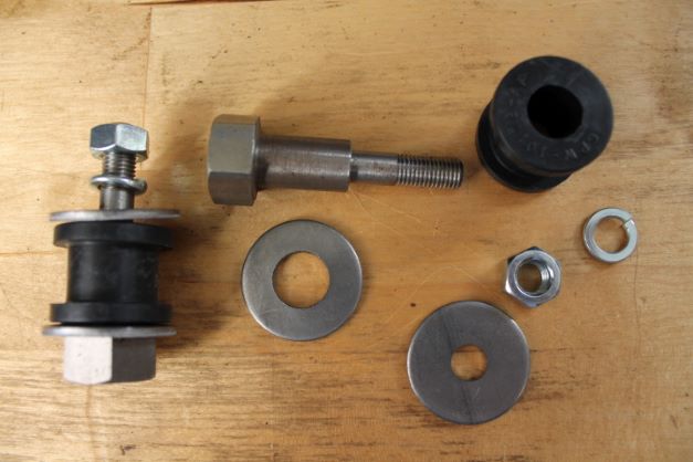
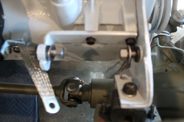
h. Installation of Generator. I used a RFJP Generator hardware kit. The rubber grommets went it fairly easily. I used a medium drift to push the rim of the grommet through the hole. Just go carefully so as not to tear the rubber. I also used a bit of greae on the bolt to slide it through. Getting the first bolt in is easy, but the other side requires the first one to be tightened to make some room for the second outer washer to be inserted between the mounting arm and the rubber grommet. It takes some work to get it in there.
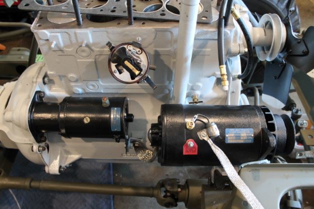
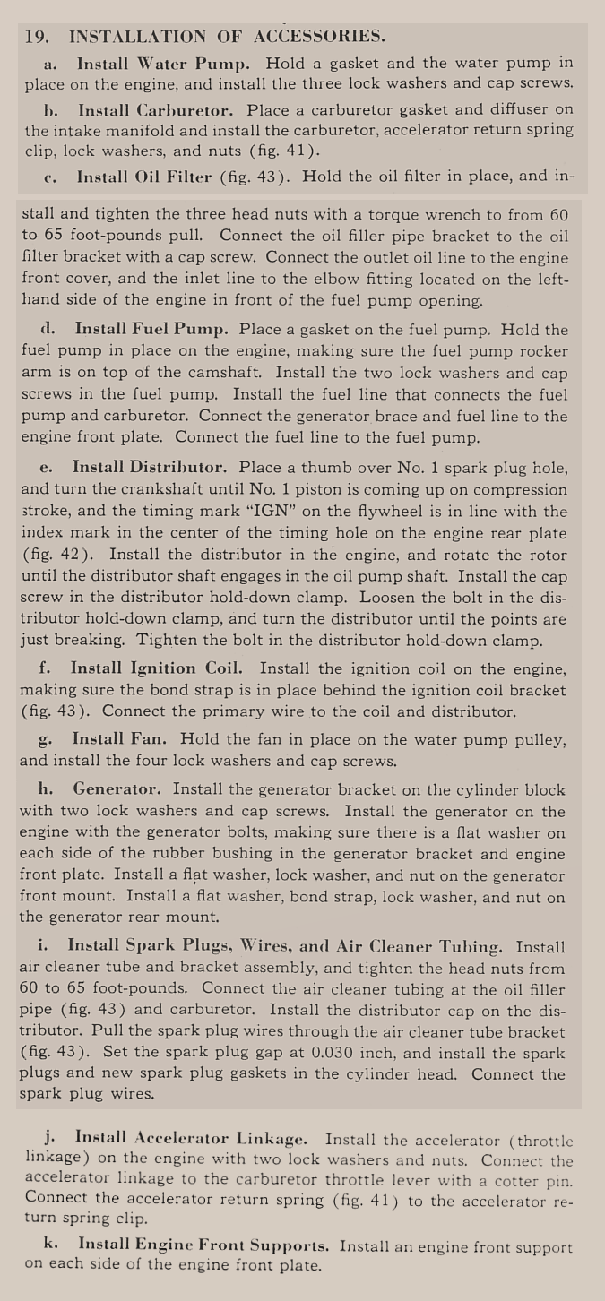
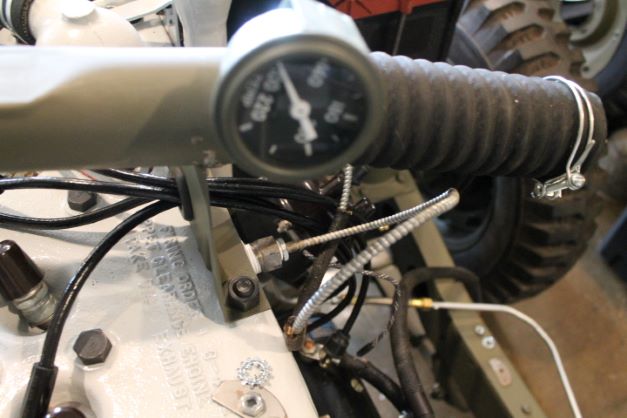
i. Install Spark Plugs, Wires and Air Cleaner Tubing. The air cleaner cross over tube is mounted below the nuts on the two studs, No 5 and 7. Te tubins is connected with two wire clamps for the flex tube and one band for the original GPW felt seal. The wires are RFJP with bakelite rain caps installed below the plug wires.
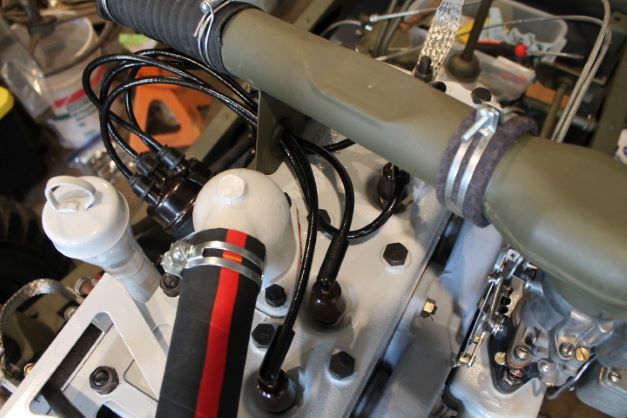
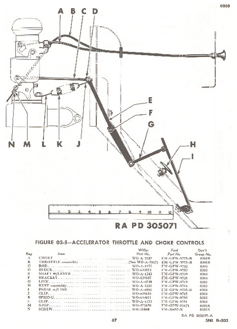
j. Install Accellorator Linkage. Here are a few diagrams/Pics to show the linkage of the Throttle and Choke Cables.
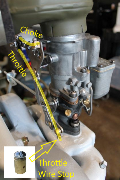
k. InstallEngine Front Supports. Those were secured when the engine was installed as shown above.
First Engine Start
There are a lot of things to consider before the first start. I am using this website, which has superb information, as a guide:
https://www.1945mb.com/article/15/G503-WWII-Jeep-Configuration-of-First-Engine-Start-after-a-Rebuild
Here are my modified steps:
- SAFETY:
- Have a fire extinguisher ready and another person to help with the start.
- Fuel Vapor is very flammable. Take care that your temporary tank is sealed but vented. Do not place it near the battery when making the final connection.
- MOUNTING: Verify all of the engine, transmission and transfer case mounting points and bonding locations are properly installed and torqued.
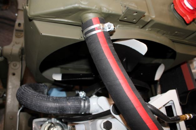
- RADIATOR: Verify that the radiator is secured by the two studs to the frame and double check the tightness of the hose clamps. Make sure any water pettcocks on the block or elsewhere are closed.
- OIL CANISTER: verify the filter is installed, the fittings are secure and all lines are properly secured. Give another chck to the block to make sure the oil galley plugs are installed and secured.
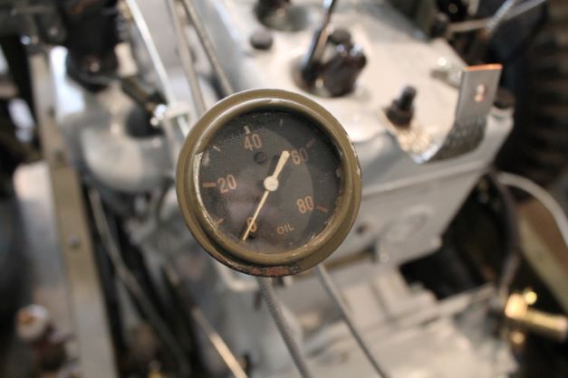
- OIL PRESSURE: Check the oil gauge line and gauge are installed and secured somewhere to the engine so you can read oil pressure.
- TEMPERATURE: Connect the temperature gauge to the block and make sure it is properly secured.
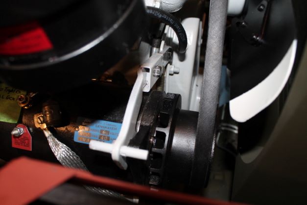
- FAN BELT: Make sure the belt tension is verified (about 1" deflection), and double check all of the generator mounting bolts and the generator tensioning arm with spring.
- COIL: Install the coil, the primary coil and secondary coil wires
- FUEL LINES: Make sure the fuel lines from the temp tank all the way to the pump and carb are secure and the fittings are tight. Any vapor from the temporary tank could ignite so use a sealed and vented system.
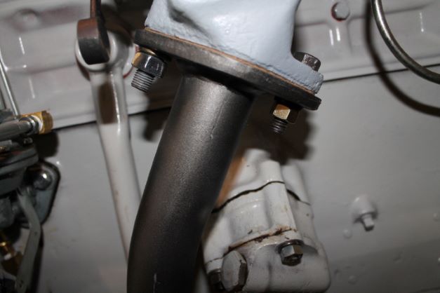
- EXHAUST: Take the opportunity to check all of the manifold and exhaust mounting points for security. Any air leak into the intake manifold will hamper a proper operation.
- TIMING:
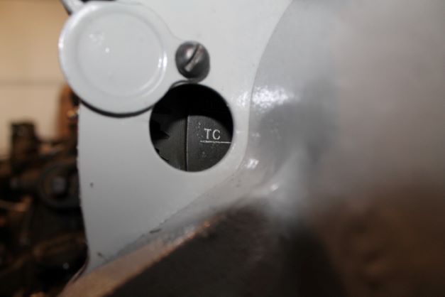
- FLYWHEEL: Ensure the engine No. 1 Piston is at TDC, and that the timing TD mark is visible in the timing inspection hole.
- POINTS: Set the gap on the points to 0.020". install a fresh rotor verifying it is pointing to the 5 O'clock position as previously checked when the dist was mater to the oil pump.
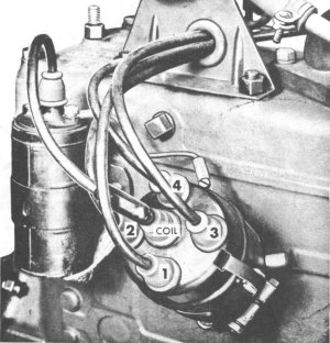
- PLUG WIRES: Ensure the spark plug wires are installed with 1 at the 5 O'clock location and then going clockwise from there install the 2, 4, and 3 plug wires verifying they go to the correct cylinder, which is from front to rear 1,2,3 and 4.
- WIRING:
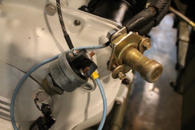
- Long + battery cable to foot starter post (Leave Battery out for now),
- Negative cable to the grounding point on the frame verified tight.
- Short, fat starter cable from other starter switch post to starter.
- + coil wire to ignition key switch.
- Other ignition key switch post connected to foot starter switch post that carries the lead from the battery.
- The - side of the coil is connected to the screw post on the distributor.
- FLUIDS:
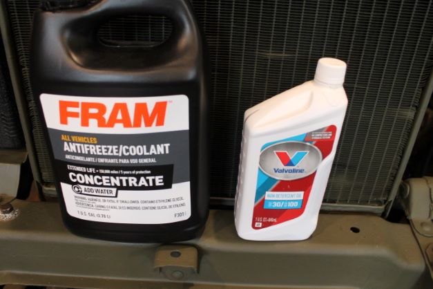
- RADIATOR: Top off the radiator. The system capacity is 11 quarts. Install a fresh radiator cap gasket.
- ENGINE OIL: The crankcase with filter change requires 5 quarts. There are a few ways to prime the oil pump. One is to crank the engine without spark plugs or ignition until oil pressure is observed. ANother is to remove the oil line from the canister and fill the oil line up by using a hand held oil squirter can unitl oil comes out of the oil gauge end. This way you ensure the entire galley, pump and lines are filled. It is also recomended to put a few CCs of oil in each cylinder before installing the plugs.
- TRANSMISSION AND TRANSFER CASE: Fill them with 90wt oil. 3/4 quarts in the transmission and 1 1/2 quart in the transfer case. While you are at it add 1 1/4 quart to each differential. I found the transmission took 22 oz, the transfer case about 34 and the differentials were just over 1 qt.
- SPARK PLUG: Gap the plugs to 0.030" and install them.
- TACHOMETER: Attach a tack gauge to set the RPM if able. I will follow the connections as described in my tach manual.
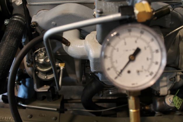
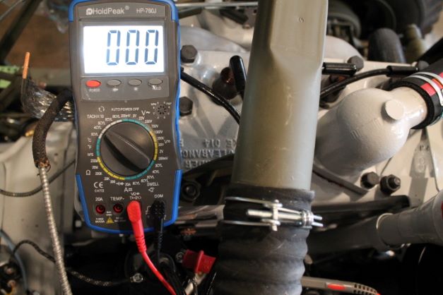
- VACUUM: If able, connect a vacuum gauge to asess the initial operation of the engeine and make an adjustment on the timing. I was fortunate to have a 1/8" NPT plug on the intake manifold. Irritating to see it has been tapped, but in retrospect, not a bad modification.
- BATTERY: Install and connect the battery.
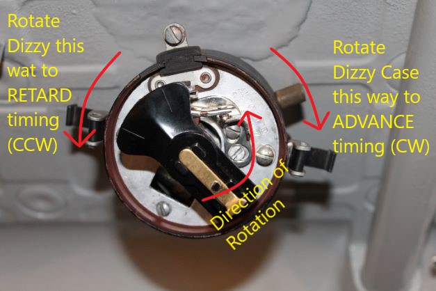
NOTE ON TIMING: . Be sure that the pointer is exactly in line with the mark on the flywheel or crankshaft pulley. Set the timing as follows: Engine Not Running. With the piston of the no. 1 cylinder on top dead center (timing marks alined), the points should be just opening. Loosen the distributor clamp and turn the housing in the direction of rotation of the distributor rotor until the points are closed. Turn on the ignition switch and hold the end of the high-tension cable that enters the distributor cap from the coil a distance of about 1/4 in. from a ground. Turn the distributor in the opposite direction to that of rotation of the distributor rotor until a spark jumps the gap from the high-tension cable to the ground. At this time the points are just opening. Clamp the distributor in this position. Turn ignition off. Engine Running. Replace the distributor cap. Attach one lead of a neon timing light to the no. 1 sparkplug without disconnecting the high-tension cable. Connect the other lead from the timing light to a convenient ground. Start the engine and run at idling speed. Direct the beam of light on the timing mark on the flywheel or crankshaft pulley. Timing light flashes will make the timing marking appear stationary. It should be directly under the pointer. If it is not in this position, the timing should be adjusted until it is. To advance the timing, rotate the distributor housing in the opposite direction from the rotation of the rotor. To retard the timing, rotate the distributor housing in the same direction as the rotation of the rotor. When the timing mark and the pointer are properly alined, clamp the distributor housing. If an ignition timing light is not available, a length of high-tension cable can be used. Place one end against the no. 1 sparkplug cable at the point where that cable comes out of the distributor. Hold the other end of the cable about 3/8 in. from the moving portion of the flywheel or crankshaft pulley. The spark jumping to ground will give much the same effect as a timing light.
First Engine Start
The first engine start was not without challenges.
1. No fuel was getting to the bowl using the manual priming lever on the JMP fuel pump. I spotted a small leak at one of the fuel line fittings that had not been tightened down properly. Air in the line prevented it from being pumped to the bowl. Problem fixed, nice squirts in the carb throat when depressing the pedal lever.
2. Would not start at all, just rotation of the starter and engine. At least the starter is working and the battery is minding well. Numerous cranks with no luck.
a. I reset the flywheel to TD with the No. 1 cyl at TDC. I checked the rotor under the cap at about 5:30 position.
b. I retraced all of the plug wires from the 5:30 position being No. 1 cylinder and then counterclockwise from 1 to 3 to 4 and then 2. I checked the cap and rotor to ensure no cracks or corrosion and all plug leads connected properly.
c. I checked the points gap at 0.020" and rotated the dizzy clockwise until the points opened, and then clockwise slightly until they began to close. I tightened the dizzy clamp down slightly.
d. I removed the HT line from the top of the coil, and with the ignition switch on I placed it near a bolt on the block while cranking and observed a nice blue spark. I have a good coil and spark coming to the dizzy (previously tested primary at 1.3 ohms and secondary at 88k ohms).
e. I reconnected the HT lead and took out the 4 spark plugs and attached them to the spark wires. Again with the ignition on I cranked and individually checked the spark from each plug against the block. 4 x blue flames. Spark plugs reinserted. At this point I am convinced that I have good spark going to each cylinder in the correct fashion.
3. Cranked again with no luck. I decided to remove the cap on the dizzy and observe the rotor while cranking, ignition off. The rotor was not moving.
4. I discovered that the spring clip was not properly allowing the dizzy shaft to seat in the oil pump slot and was essentially not rotating. I removed the spring for now, reset everything and voila, she fired up. I will have to research why this is despite having lightly filed the clips corners down. SOmething is preventing the dizzy from fully seating into the slot when the clip is attached. I will not leave it out and will try and find why this is.
Problems to address.
1. Oil leak between the block and oil pump. WIll drain and remove the oil pump and install new gasket with better sealer and instead of using studs and nuts, will go with bolts and lock washers.
2. Engine was running rough initially. The dizzy was rotating from the original position as the engine ran. When I returned it to original setting, it ran much more smoothly. I tightened down the dizzy clamp a bit more, but loose enough so I can make small adjustments later.
3.Very minor seeping from one of the water elbow bolts. I think that will seal itself in a few hours of run time.
Little Victories to savor.
1. Its alive!
2. The oil pressure was 42 at idle and 60 at higher RPM. For the 5 minutes the engine ran it never dipped below 40. This is with an original GPW pump, restored with a NOS pump rebuild kit. Yes it can be done Virginia.
3. I watched the engine temperature approach and never get above 160. It was cold outside.
4. I was able to give all 15 cylinder stud nuts and bolts a re-torque while the engine was hot. I am amazed at how the heat makes them seem loose. Felt like back to 55 ft-lbs or so.
5. So far the rear main seal is not leaking, but I will investigate later. No other engine leaks.
6. All indications of strong flow of electrons through all of the components and bonding points.
Air FIlter Installation
My GPW is early April 1942. The correct air filter would be either the Houde canister with the decal or the canister with the data plate welded on. The later version had the data plate information embossed into the canister. The decal ceased useage some whaere around the end of March or beginning of April. My GPW is from 9 April, so the decal filter canister would be possible. Since they are rare, and I have one I installed it here. Unfortunately the decal is not at 100%, but I elected to retain the original verses covering it with a reproduction decal. The canister is cleaned and repainted.

Adjusting the Engine Timing
Now that I have the oil pump leak fixed, I can focus on tuning the engine. I have connected my vaccum gauge back up along with a digital dwell and tach., I used the following G503 Thread to get these steps:
https://forums.g503.com/viewtopic.php?t=247709
- Connect the vacuum gauge to an inlet vacuum source
- Set Points Gap to 0.020"
- Set timing to 5 degreews BTDC (IGN Mark)
- Set the motor to the IGN position with the rotor at the 5:30 position
- Slightly loosen dizzy clamp and remove rotor clap
- Turn dizzy case by hand CCW until points are together
- Turn ignition switch on
- Tun dizzy case by hand CW unitl the points spark. This is the point of ignition you want for a good start.
- Tighten the dizzy clamp so it does not migrate while running.
- Set the Idle Mixture Screw all the way in and then back out exactly 1 1/2 turns.
- Start the motor.
- Adjust the idle mixture screw out (enriching) or in (leaning) to get teh highest vacuum reading. No more than 1/4 turn max either way.
- Adjusat he dizzy case slightly CW and CCW until the highest vacuum reading is obtained.Retard the dizzy slightly (CCW) until the vacuum reads about 1/2" less.
- Tighten the dizzy clamp fully.
I started the engine for the second time. It started relatively quickly on the static timing setting as described above. The oil leak at the pump gasket is remedied. Here is waht I learned from attempting to adjust the timing.
- My carb was set up by the rebuilder, so I made no adjustments to it. I will try that on the third start.
- I checked the dwell using my digital gauge. It varied from 39.9 to 40.9. L-134 Dwell is supposed to be 42 degrees. I'm close.
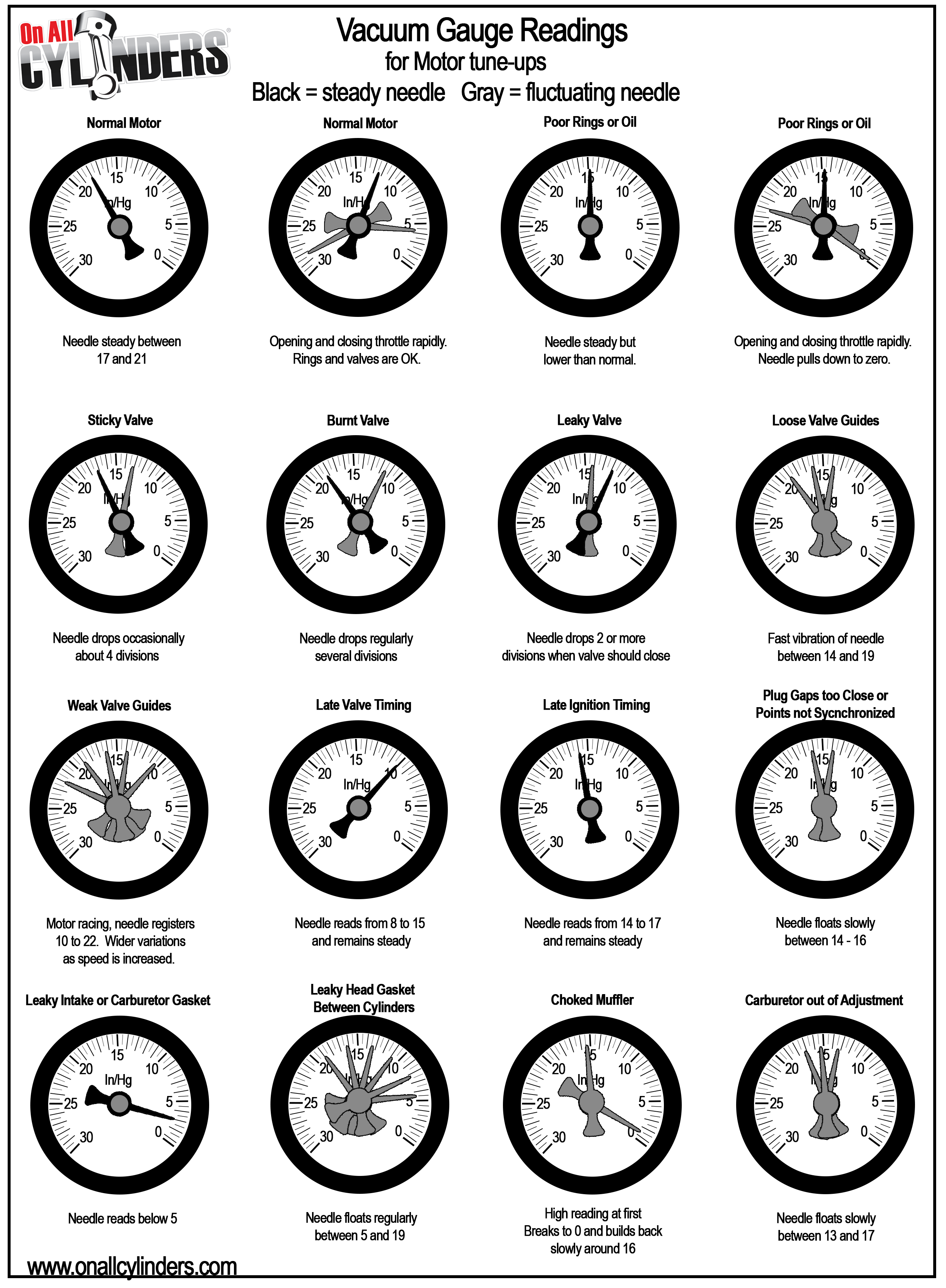
- Vacuum reading at idle was approximately 17" at 1000'MSL (- 1" per 1000' elevation gain). Normal reading at my elevation should be 17-20". I am at the bottom of the reading, but in the acceptable range. There is a steady fluctuation of about 1/2" which I understand is within the normal range.
- I went right to adjusting the dizzy case and ended up having the timing so advanced that it did not want to start. I returned it to the IGN location with just a bit of advacned timing to ease the start.
