Tear Down
BEFORE
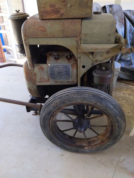
AFTER
General
I began taking off varoius panels and components keeping everything bagged and boxed. I am taking several pictures to help in assembly later.
Removal of Engine Air Filter
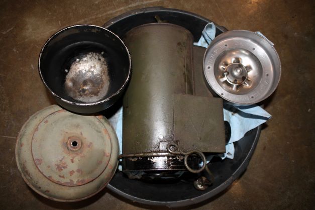
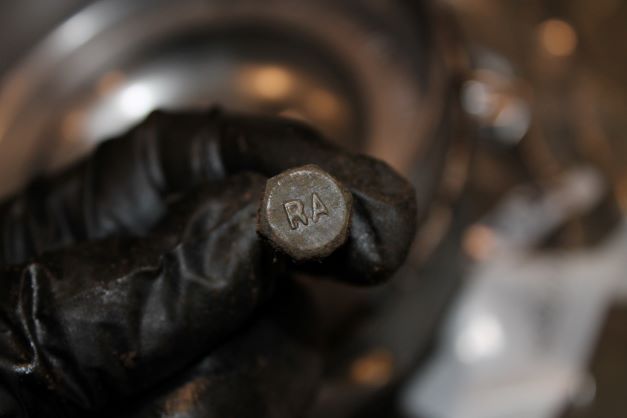
The air filter came off with little effort. There was a screw hiding under the upper lip of the frame that required a bit of heat to remove. The oil in the filter was nice and clean. The filter housing is painted semi gloss black under OD. The 4 5/16 bolts are RA marked and secured with a nut and lock washer.
Front Panel Details
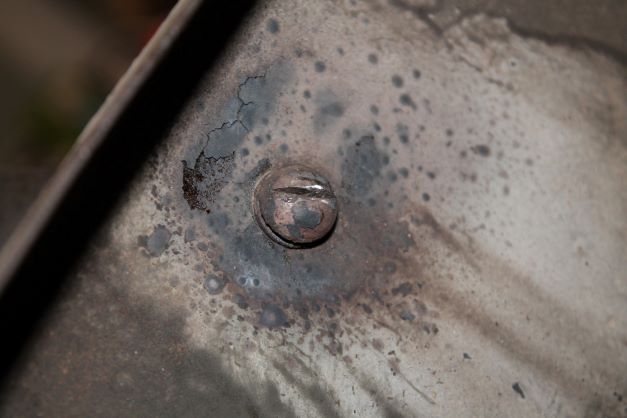
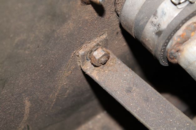
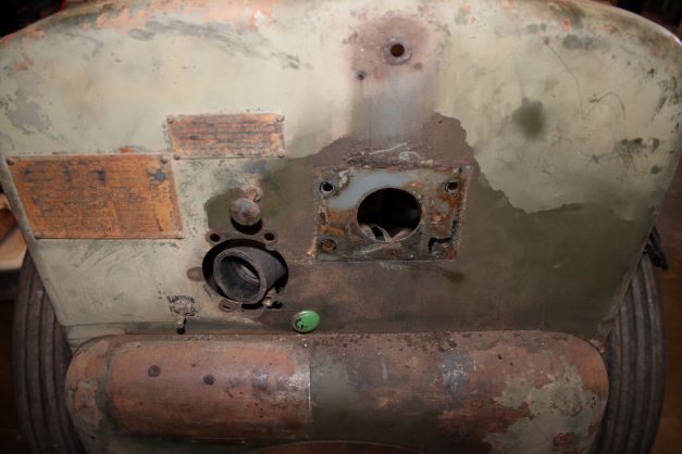
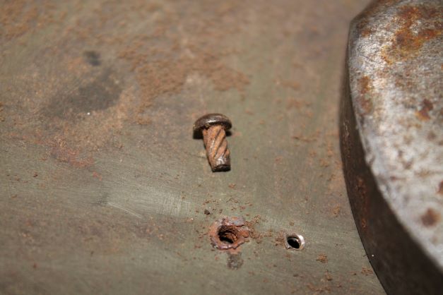
The front panel has 3 different types of hardware connecting it to the chassis. There are; 4 unmarked 1/4 x 5/8" CT bolts with a hex nut and split lock washer on either side, 5 sheet metal or tapping screws No 8, and 2 1/4 x 5/8" sheet metal screws with a recessed hex head in 3/8 size.
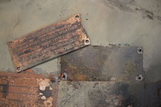
The small data plate is held on with 4 No. 2 1/4" screws and split lock washer and the larger data plate has 4 rivets as seen in the image.
There is a kill switch labled TO STOP PULL OUT. It is made in Milwuakee, by CLUM. Ill have to do some research on that
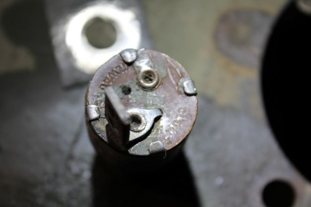
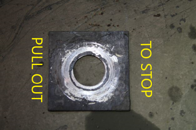
Manifolds
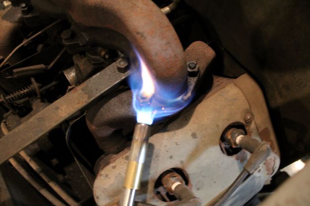
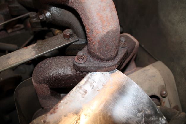
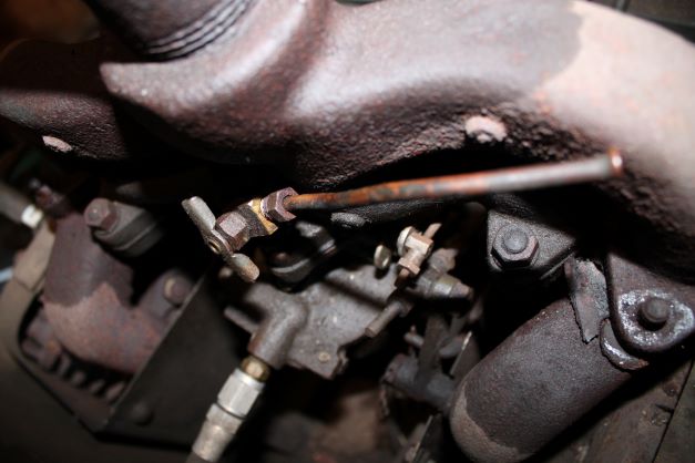
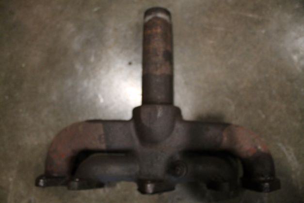
This area can always be problematic with rusted studs and bolts. Trying to be patient I sprayed some PB Blasted on all nuts and let them sit overnight. In the morning I used some butane heat and a bit more of the PB before attempting to loosen the 8 nuts. I have broken a few manifold studs and they are not fun to remove, so this is a prcaution well worth the wait. There is a split L/W under each nut. I did not want to break the ears off so i used heat, more PB and a flat scraper to work between the manifold and the heads. It took a lot of time to get them apart. Iremoved the two wing brackets that were in the way. Each was secured with 6 bolts and 12 L/Ws. There were two more bolts that secured the carburetor to the bottom of the intake manifold.
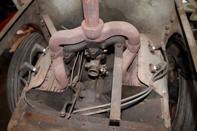
Carburetor
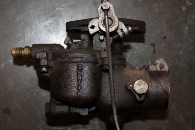
The carburetor is secured to the bottom side of the intake manifold with two RA marked bolts. These pass through the top of the manifold ears and thread into the carby. There were two more bolts that secured the carburetor to the bottom of the intake manifold. The carb is a Zenith S-632 model with many rebuild kits available.
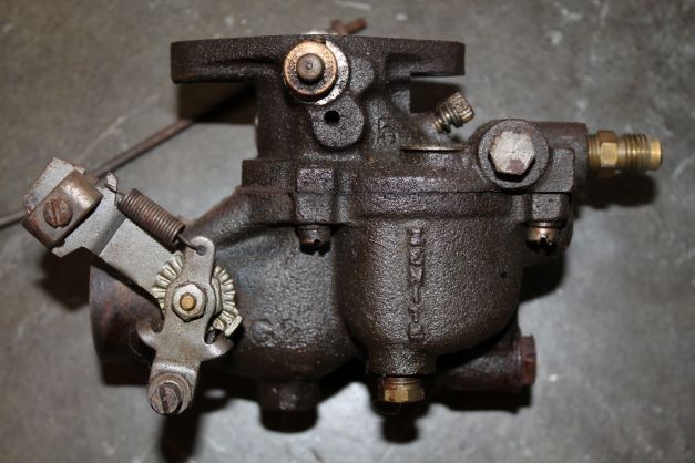
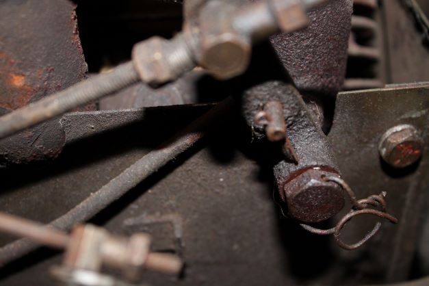
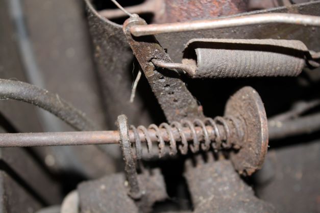
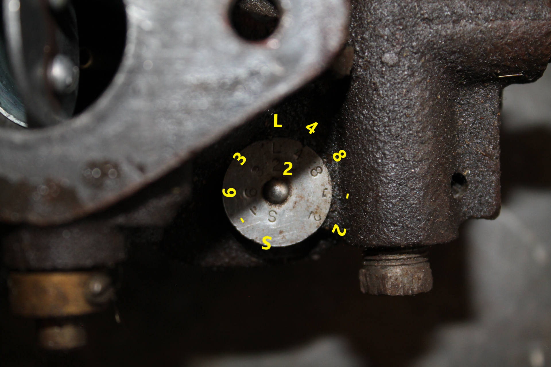
Ignition Wires and Heat Shield
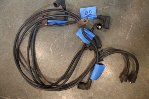
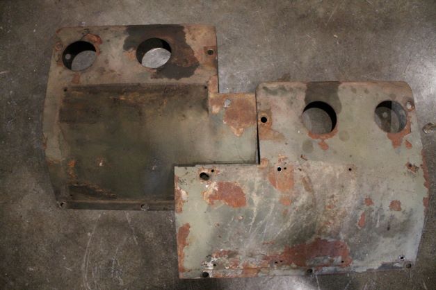
I labled the Ignition Wires not by cylinder number but by location. I also removed the two cylinder heat shields. THere are two clamps and screws to hold the wires to the heat shield.
Removal of Flywheel, Shroud and Cover
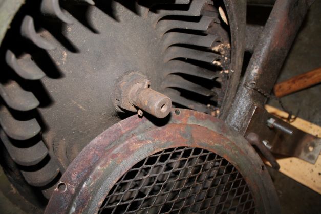
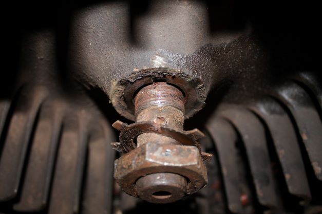
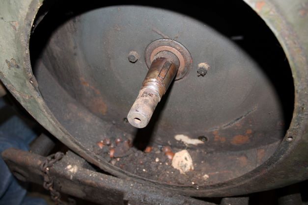
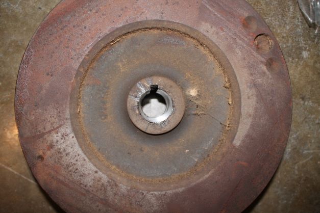
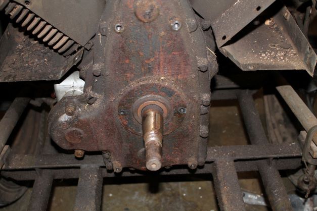
The TM says after removal of the flywheel front cover, remove the cranking pin with a drift after loosening the set screw and then remove the nut and give the shaft a hit and the flywheel will slide off the tapered shaft. Easier than it sounds as this has been on there for nearly 80 years. I had to completely loosen the outer shroud so I could rap on it which drove the flywheel off the shaft. There was nothing to grip with a puller and heat helped a bit. All of the shroud bolts are RA marked with L/Ws.
Removal of Compressor Fan Shroud and Fan
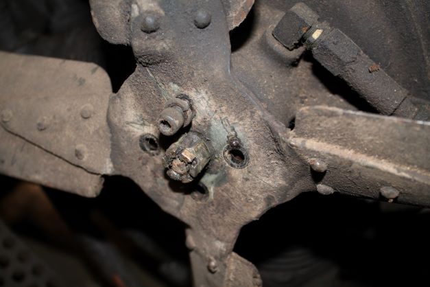
Removing the fan shroud and fan was simple. There are 4 hex slotted screws that hould the shroud to the compressor and a single hex head bolt at the bottom which holds the shroud to the frame.
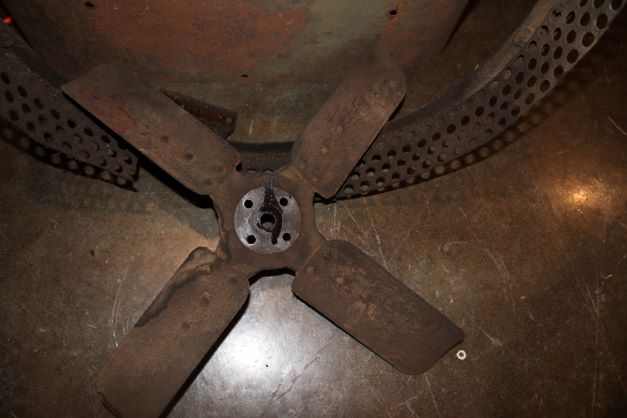
Removal of Compressor
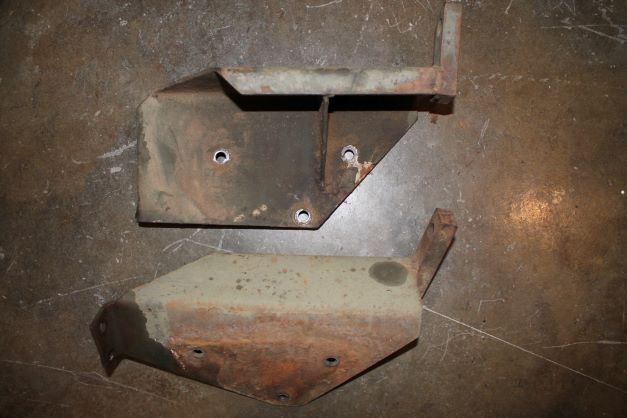
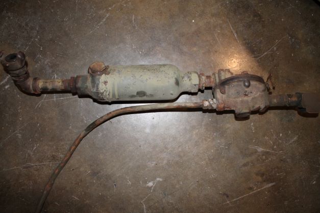
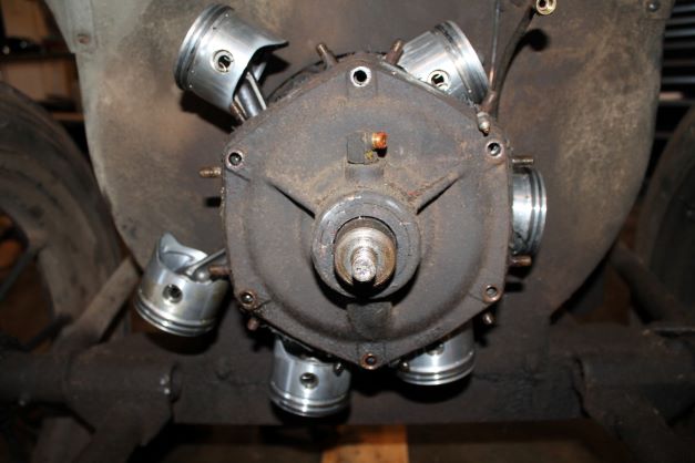
There is a lot of work here to get all of the pneumatic piping removed as well as the individual cylinders. I will begin by removing the side braces next to the fuel tank. At the rear is the set of piping consisting of the hose coupling, lubricator and discharge unloader. After removing that assembly I was able to take off the left and right tank brackets each led on by 3 1/2" CT bolts with a larger nut and 2 lock washers each. As a side note the TM recommends instaling the same cylinder in the original position it was removed from. I will number them with a punch. Each cylinder is interconnected with plates, pipes and air cleaners.
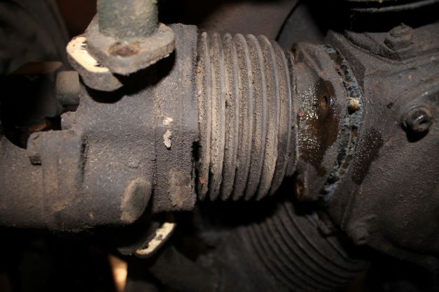
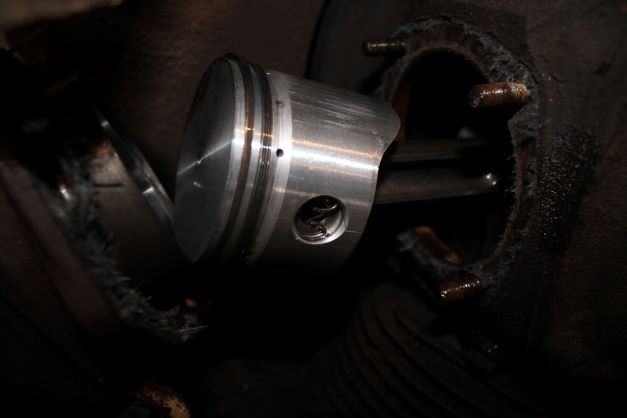
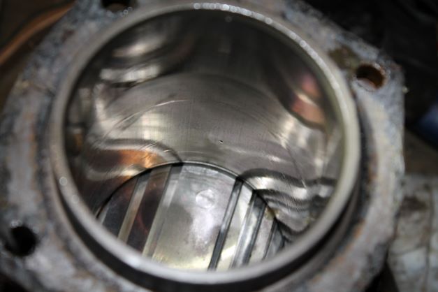
The TM also specifies removal of the cylinder heads before the cylinders. It is a tight fit to get the whole cylinder out with out removing the head. The coupling (Front nut) and ket were hard to remove as well. A puller was needed.
Removal of the crank case end cover was a bit problematic. I suspect being seated for 80 years made the job difficult. I did not want to damge any of the ears, so I took my time and used a bit of heat and WD40.
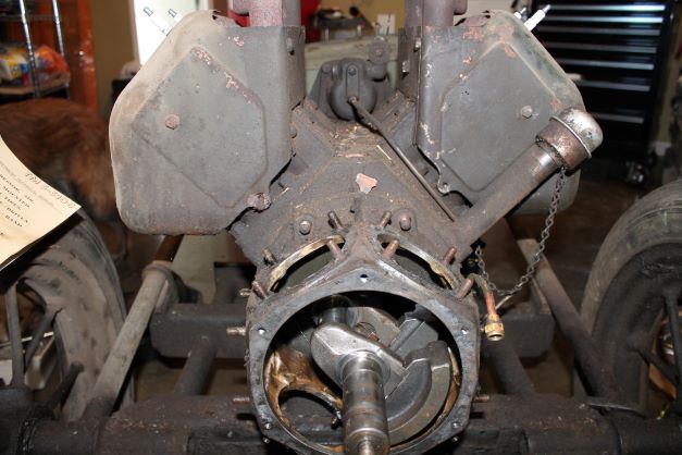
The removal revealed the brilliant design of the two rod groups and their design using one set of bearings.
Once I had all of the pistns and rods removed, I was able to take the fuel tank bracket and tank off. Were getting closer to removing the engine so I can take the frame and rest for sand blasting.
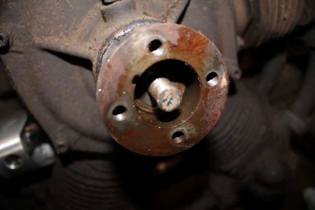
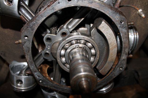
Engine Removal
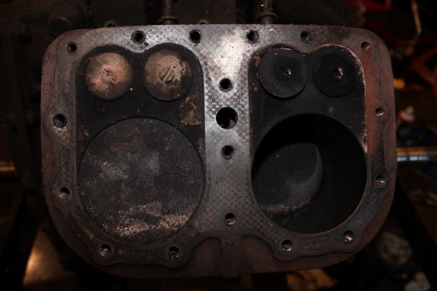
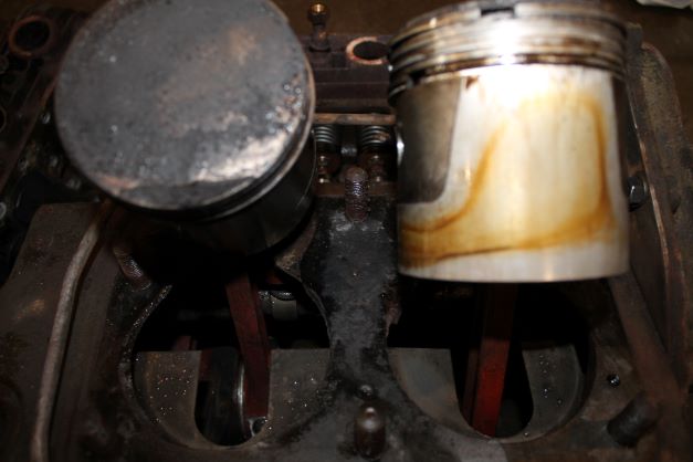
I removed the metal shrouds that surround the cylinders and gently loostened the head screws. Ill take my time here so as not to snap any bolts. So far everthing is coming off easily. The first cylinder bore I measured was 3.250". That is standard per the TM, so these cylinders has not beeN rebored as far as I can tell. Judging by the carbon build up it has seen a reasonable amount of use to date.
Engine Tear Down
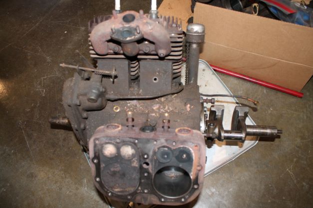
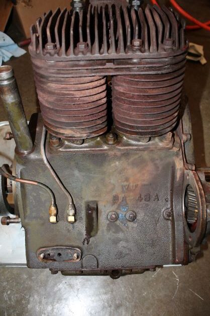
The engine block was really grimy. I used some engine degreaser and my pressure washer to clean it up a bit. The block is painted OD, and the cylinders and heads are rusty, so no color can be deduced. I will either use OD or black for them. I plan on taking the block to the machine shop and getting it baked and cleaned and a light honing for the cylinders applied. I do not ecpect much more will be needed.
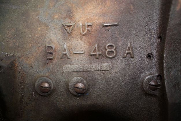
BA-48A is the casting number for the VF-4 engine.. I can determine nothing else regarding the FOundry ID above and the date boss below.
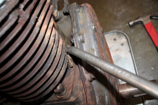
There are a couple of cylinder nuts that are tucked under fins that are hard to remove. I found the angled 5/8" wrench in the original tool kit worked great for getting in the tight spaces.
Engine Gear Cover Removal
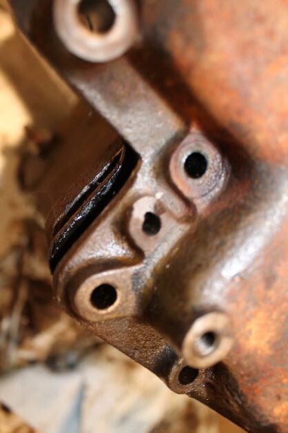
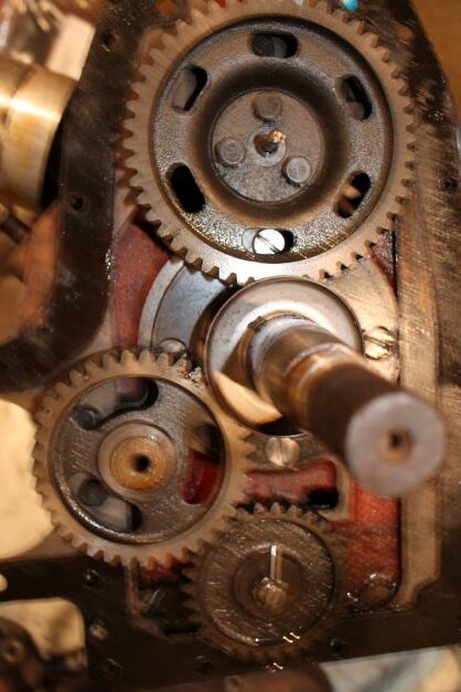
There are several bolts and two dowwel pins that hold the Timing Gear COver to the block. The bolts came right off, but the two dowwell pins were a bear to remove. Drift pins and heat did nothing. I had to wedge two brass wedges between the block and cover to slowly pry the pins out. They are part of the cover. It will take some time to remove the pins from the cover. O small part of one of the pin lips broke off, but it should not cause a problem.
Engine Block Cleaning
I finished stripping the engine, degreased it and used a pressure washer to clean up the mess. Removing the oil galley plugs was a bit of a problem as they have flad head screws in stead of pipe plugs.
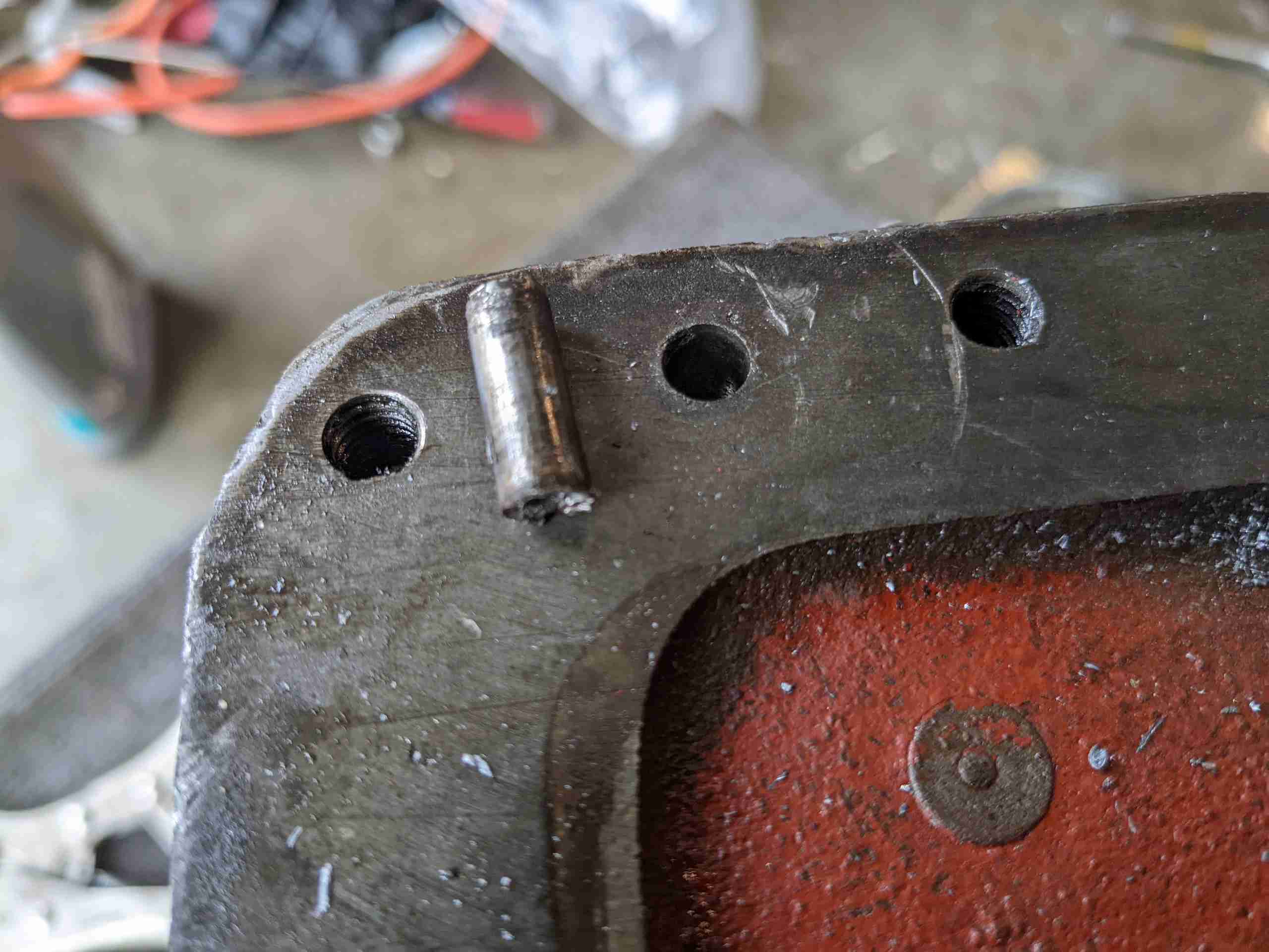
I was also able to remove a stuck timing cover dowel pin by center drilling it and punching it out. It measures 0/250"
Frame and Wheels
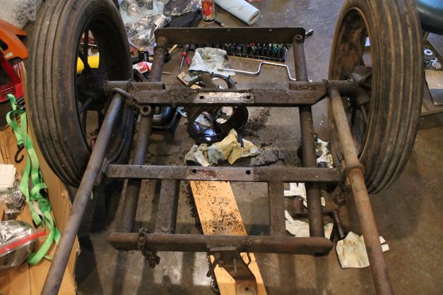
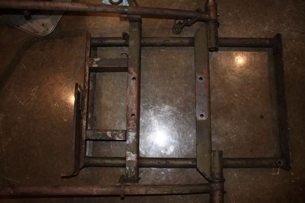
The frame and wheels are fairly simple. I'll remove the wheels, tires and clean and blast the frame and rims. I have new 4.00 x 18 tires and tubes on order. Tires are not a great match as far as the rib configuration goes. The tubes need an RT-13 offset stem. There was a heavy layer of grease and grime so I pressure washed the frame and wheels. It appears that IR painted all components black, and then used red oxide over the frame and then OD. The wheels did not get red oxide.
Gauge Removal
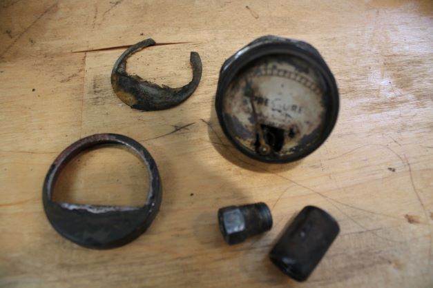
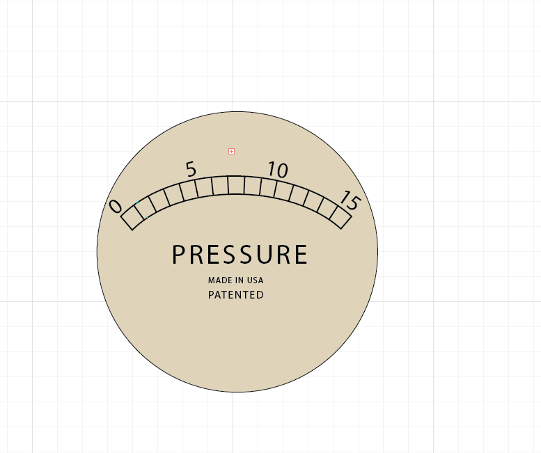
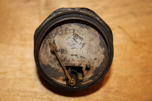
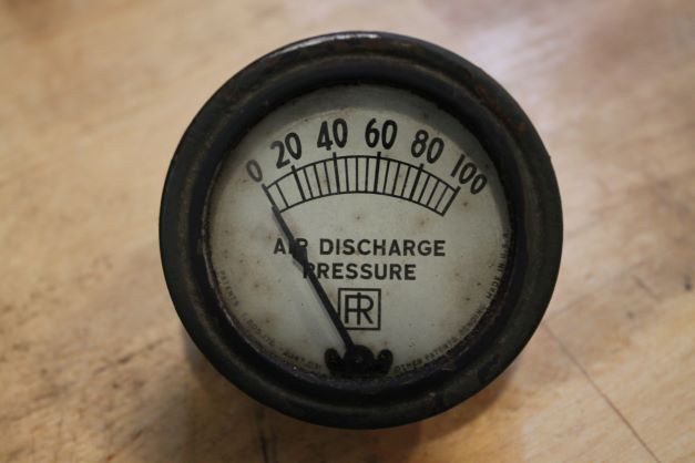
The tiny Oil Pressure Gauge has seen better days. The face is worn and the plastic covering the dial is deteriorated. The face plate is 1.40" in diameter and I have looked for over a year to find a matching one. No luck. I will print a new face using Adobe Illustrator. and see how well I can match it. The Air Pressure Gauge is an Ingersoll-Rand gauge and seems to be in great shpe. Just a clean up and case painting required.
Place Holder
Place holder